
General Description
This piston pump is a precision power tool used for spraying
many types of materials. Read and follow this instruction
manual carefully for proper operating instructions,
maintenance, and safety information.
Operation
This equipment produces a fluid stream at extremely high
pressure. Read and understand the warnings in the
Safety Precautions section at the front of this manual
before operating this equipment.
Setup
Perform the following procedure before plugging in the power
cord of an electric unit.
1. Ensure that the suction set and the return hose are
attached and secure.
2. Attach a minimum of 50’ of nylon airless spray hose to the
unit.
3. Attach an airless spray gun to the spray hose. Do not
attach the tip to the spray gun yet. Remove the tip if it is
already attached.
Make sure all airless hoses and spray guns are electrically
grounded and rated for at least 3200 psi (220 bar) fluid
pressure.
4. Turn the pressure control knob fully counterclockwise to
its lowest pressure setting.
5. Make sure the ON/OFF switch is in its OFF position.
6. Fill the wet cup with one tablespoon of piston seal
lubricant (Piston Lube).
Never operate unit for more than ten seconds without
fluid. Operating this unit without fluid will cause
unnecessary wear to the packings.
7. Make sure the electrical service is 120V, 15 amp
minimum.
8. Plug the power cord into a properly grounded outlet at
least 25’ from the spray area.
Always use a minimum 12 gauge, three-wire extension cord
with a grounded plug. Never remove the third prong or use
an adapter.
CAUTION
CAUTION
WARNING
WARNING
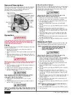
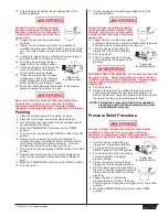
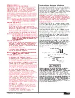
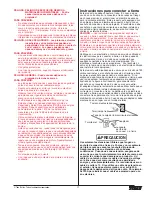
Electrical
Box
Outlet
Fitting
Filter
Siphon
Hose
Return
Tube
Pressure
Control
Knob
Motor
PRIME/
SPRAY
Valve
Fluid
Section
4
© Titan Tool Inc. All rights reserved.
Preparing a New Sprayer
If this unit is new, it is shipped with test fluid in the fluid section
to prevent corrosion during shipment and storage. This fluid
must be thoroughly cleaned out of the system with mineral
spirits before you begin spraying.
Always keep the trigger lock on the spray gun in the
locked position while purging the system.
1. Place the suction tube into a container of mineral spirits.
2. Place the return hose into a metal waste container.
3. Turn the pressure control knob fully counterclockwise to
its lowest pressure setting.
4. Move the PRIME/SPRAY valve down to the PRIME
position.
5. Turn the unit on by moving the ON/OFF switch to the ON
position.
6. Slowly turn the pressure control knob clockwise to
increase the pressure until fluid starts to come out of the
return hose. Use only enough pressure to keep the fluid
coming out.
7. Allow the sprayer to run for 15–30 seconds to flush the
test fluid out through the return hose and into the waste
container.
8. Turn the pressure control knob fully counterclockwise to
its lowest pressure setting.
9. Turn the unit off by moving the ON/OFF switch to the OFF
position.
Preparing to Paint
Before painting, it is important to make sure that the fluid in the
system is compatible with the paint that is going to be used.
Always keep the trigger lock on the spray gun in the
locked position while preparing the system.
1. Place the suction tube into a container of the appropriate
solvent. Examples of the appropriate solvent are water for
latex paint or mineral spirits for oil-based paints.
2. Place the return hose into a metal waste container.
3. Turn the pressure control knob fully counterclockwise to
its lowest pressure setting.
4. Move the PRIME/SPRAY valve down to the PRIME
position.
5. Turn the unit on by moving the ON/OFF switch to the ON
position.
6. Slowly turn the pressure control knob clockwise to
increase the pressure until fluid starts to come out of the
return hose. Use only enough pressure to keep the fluid
coming out.
7. Allow the sprayer to run for 15–30 seconds to flush the old
solvent out through the return hose and into the metal
waste container.
8. Turn the pressure control knob fully counterclockwise to
its lowest pressure setting.
9. Turn the unit off by moving the ON/OFF switch to the OFF
position.
10. Move the PRIME/SPRAY valve up to the SPRAY position.
11. Turn the unit on.
NOTE: Make sure that the spray gun does not have a
tip or tip guard installed.
CAUTION
NOTE: Incompatible fluids and paint may cause the
valves to become stuck closed, which would
require disassembly and cleaning of the
sprayer’s fluid section.
CAUTION