

Cleanup
Special cleanup instructions for use with flammable
solvents:
• Always flush spray gun preferably outside and at least one
hose length from spray pump.
• If collecting flushed solvents in a one gallon metal
container, place it into an empty five gallon container, then
flush solvents.
• Area must be free of flammable vapors.
• Follow all cleanup instructions.
The pump, hose, and gun should be cleaned thoroughly
after daily use. Failure to do so permits material to cake,
seriously affecting the performance of the unit.
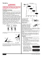
Always spray at minimum pressure with the gun nozzle tip
removed when using mineral spirits or any other solvent
to clean the pump, hose, or gun. Static electricity buildup
may result in a fire or explosion in the presence of
flammable vapors.
1. Follow the “Pressure Relief Procedure” found in the
Operation section of this manual.
2. Remove the gun tip and tip guard and clean with a brush
using the appropriate solvent.
3. Place the suction tube into a container of the appropriate
solvent. Examples of the appropriate solvent are water for
latex paint or mineral spirits for oil-based paints.
4. Place the return hose into a metal waste container.
5. Move the PRIME/SPRAY valve down to its PRIME
position.
6. Turn the unit on by moving the ON/OFF switch to the ON
position.
7. Slowly turn the pressure control knob clockwise to
increase the pressure until fluid starts to come out of the
return hose. Use only enough pressure to keep the fluid
coming out.
8. Allow the solvent to circulate through the unit and flush
the paint out of the return hose into the metal waste
container.
9. Turn the unit off by moving the ON/OFF switch to the OFF
position.
10. Move the PRIME/SPRAY valve up to its SPRAY position.
11. Turn the unit on.
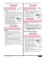
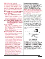
Ground the gun by holding it against
the edge of the metal container while
flushing. Failure to do so may lead to
a static electric discharge, which may
cause a fire.
12. Trigger the gun into the metal waste
container until the paint is flushed out of the hose and
solvent is coming out of the gun.
13. Continue to pull and release the trigger until the solvent
coming out of the gun is clean.
NOTE: Pulling and releasing the trigger of the spray
gun creates a “pulsing” action that cleans out
the hose and the spray gun more effectively.
WARNING
WARNING
CAUTION
WARNING
14. Follow the “Pressure Relief Procedure” found in the
Operation section of this manual.
15. Unplug the unit and store in a clean, dry area.
Do not store the unit under pressure.
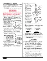
Maintenance
Before proceeding, follow the Pressure Relief Procedure
outlined previously in this manual. Additionally, follow all
other warnings to reduce the risk of an injection injury,
injury from moving parts or electric shock. Always unplug
the sprayer before servicing!
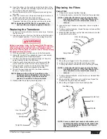
General Repair and Service Notes
The following tools are needed when repairing this sprayer:
Phillips Screwdriver
3/8" Hex Wrench
Needle Nose Pliers
5/16" Hex Wrench
Adjustable Wrench
1/4" Hex Wrench
Rubber Mallet
3/16" Hex Wrench
Flat-blade Screwdriver
5/32” Hex Wrench
1. Before repairing any part of the sprayer, read the
instructions carefully, including all warnings.
Never pull on a wire to disconnect it. Pulling on a wire
could loosen the connector from the wire.
2. Test your repair before regular operation of the sprayer to
be sure that the problem is corrected. If the sprayer does
not operate properly, review the repair procedure to
determine if everything was done correctly. Refer to the
Troubleshooting section to help identify other possible
problems.
3. Make certain that the service area is well ventilated in
case solvents are used during cleaning. Always wear
protective eyewear while servicing. Additional protective
equipment may be required depending on the type of
cleaning solvent. Always contact the supplier of solvents
for recommendations.
4. If you have any further questions concerning your TITAN
Airless Sprayer, call TITAN:
Customer Service (U.S.) .......................
1-800-526-5362
Fax ................................................
1-800-528-4826
Customer Service (Canada) ..................
1-800-565-8665
Fax ................................................
1-905-856-8496
Customer Service (International)...........
1-201-337-1240
Fax ................................................
1-201-405-7449
CAUTION
WARNING
CAUTION
NOTE: For long-term or cold weather storage, pump
mineral sprits through the entire system.
For short-term storage when using latex paint,
pump water mixed with Titan Liquid Shield
through the entire system (see the Accessories
section of this manual for part number).
© Titan Tool Inc. All rights reserved.
7


