


Maintenance
Before proceeding, follow the Pressure Relief Procedure
outlined previously in this manual. Additionally, follow all
other warnings to reduce the risk of an injection injury,
injury from moving parts or electric shock. Always
unplug the sprayer before servicing!
General Repair and Service Notes
The following tools are needed when repairing this sprayer:
Phillips Screwdriver
3/8" Hex Wrench
Needle Nose Pliers
5/16" Hex Wrench
Adjustable Wrench
1/4" Hex Wrench
Rubber Mallet
3/16" Hex Wrench
Flat-blade Screwdriver
5/32” Hex Wrench
1. Before repairing any part of the sprayer, read the
instructions carefully, including all warnings.
Never pull on a wire to disconnect it. Pulling on a wire
could loosen the connector from the wire.
2. Test your repair before regular operation of the sprayer to be
sure that the problem is corrected. If the sprayer does not
operate properly, review the repair procedure to determine if
everything was done correctly. Refer to the Troubleshooting
Charts to help identify other possible problems.
3. Make certain that the service area is well ventilated in
case solvents are used during cleaning. Always wear
protective eyewear while servicing. Additional protective
equipment may be required depending on the type of
cleaning solvent. Always contact the supplier of solvents
for recommendations.
4. If you have any further questions concerning your TITAN
Airless Sprayer, call TITAN:
Customer Service (U.S.) .......................
1-800-526-5362
Fax ................................................
1-800-528-4826
Customer Service (Canada) ..................
1-800-565-8665
Fax ................................................
1-905-856-8496
Customer Service (International)...........
1-201-337-1240
Fax ................................................
1-201-405-7449
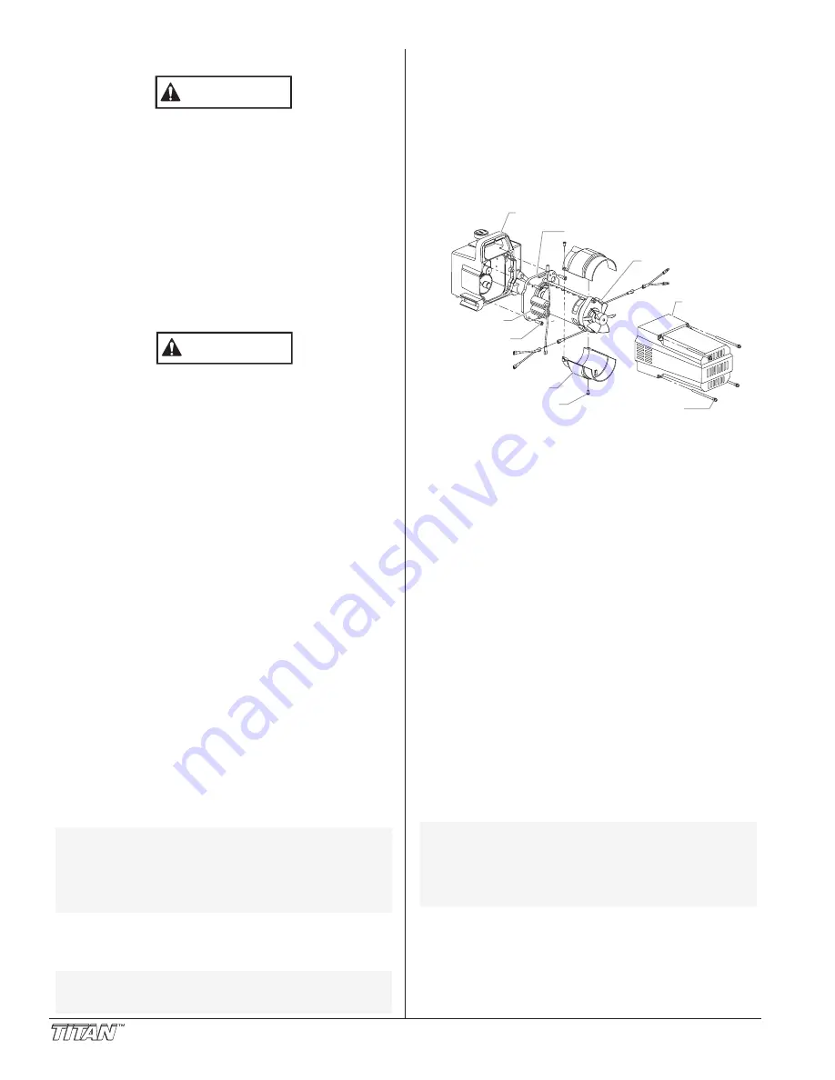
Replacing the Motor
1. Unplug the unit.
2. Loosen and remove the four motor cover screws.
Remove the motor cover.
3. Disconnect the black and red wires coming from the pump
housing. Disconnect the black and red wires from the
capacitors. Disconnect the black and red wires from the
motor.
4. Remove the capacitors from their mounting clip.
5. Loosen and remove the four motor mounting screws.
6. Pull the motor out of the pump housing.
7. With the motor removed, inspect the gears in the pump
housing for damage or excessive wear. Replace the
gears, if necessary.
8. Install the new motor into the pump housing.
NOTE: Rotate the motor fan manually until the
armature gear engages with the mating gear in
the pump housing.
NOTE: If the motor will not dislodge from the pump
housing:
• Remove the front cover plate.
• Using a rubber mallet, carefully tap on the
front of the motor crankshaft that extends
through the connecting rod.
CAUTION
WARNING
8
© Titan Tool Inc. All rights reserved.
9. Secure the motor with the four motor mounting screws.
10. Using the double-sided tape and the tie wrap that came
with the new motor, attach the capacitors to the motor.
a. Place the double-side tape on the capacitors, and stick the
capacitors onto the motor. The capacitors should be
positioned in the same spot as they were on the old motor.
b. Wrap the tie wrap around the capacitors and the motor.
11. Reconnect the wires (refer to the electrical schematic in
the Parts List section of this manual).
12. Slide the motor cover over the motor. Secure the motor
cover with the four motor cover screws.
Replacing the Motor Brushes
Perform this procedure using Motor Brush Kit P/N 704-276.
1. Loosen and remove the four motor cover screws.
Remove the motor cover.
2. Loosen and remove the two shroud screws. Remove the
shroud.
3. Using a small screwdriver, pry off the two plastic brush
covers.
4. Disconnect the black and red wires from the motor
brushes. Remove the motor brushes.
5. Install the new motor brushes and snap on the plastic
brush covers.
6. Reconnect the black and red wires from the motor
brushes (refer to the electrical schematic in the Parts List
section of this manual).
7. Position the shroud over the motor fan. Secure the
shroud with the two shroud screws.
8. Slide the motor cover over the motor. Secure the motor
cover with the four motor cover screws.
Replacing the Gears
1. Loosen and remove the four motor cover screws.
Remove the motor cover.
2. Disconnect the black and red wires coming from the pump
housing.
3. Loosen and remove the four motor mounting screws.
4. Pull the motor out of the pump housing.
5. Inspect the armature gear on the end of the motor for
damage or excessive wear. If this gear is completely
worn out, replace the entire motor.
6. Remove and inspect the 2nd stage gear for damage or
excessive wear. Replace if necessary.
7. Remove and inspect the gear and crank assembly for
damage or excessive wear. Replace if necessary.
NOTE: If the motor will not dislodge from the pump
housing:
• Remove the front cover plate.
• Using a rubber mallet, carefully tap on the
front of the motor crankshaft that extends
through the connecting rod.
BLACK
BLACK
BLACK
RED
RED
RED
Motor Cover
Brush Cover
Motor
Pump Housing
Capacitors
Motor Mounting
Screw
Shroud
Shroud Screw
Motor Cover
Screw


