background image

© Titan Tool Inc.  All rights reserved. 

7

Setup

Read, understand, and follow all warnings before 

starting or operating this sprayer.

Required tools:  adjustable wrench

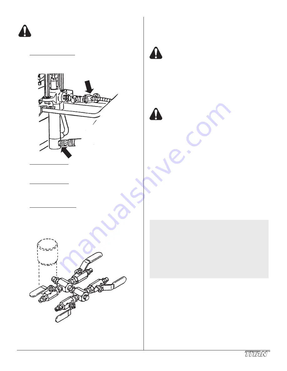
1. connecting the hoses:

The siphon hose and bleed line hose have factory 

installed 

PTFE

 tape on the male end o

f

 the hoses.  

Tighten the siphon hose and bleed line wrench tight.   

2. One gun operation:

Attach the gun and hose.  Always use a spray hose at 

least 50 feet long.  Do not use

 PTFE

 or thread sealant on 

this assembly.  Do not install the spray tip at this time.

3. Two gun operation:

Remove the plug from the second gun outlet.  Replace 

with nipple, part # 812-003 for 1/4” hose or nipple; use part 

# 808-555 for 3/8” hose.  Connect a hose and a gun to the 

outlet. 

4. Multiple gun operation:

The Hydra M 4000™ is engineerd to handle up to 4 guns. 

When using more than two guns, make sure the second 

gun hookup outlet is plugged.  Connect the multiple gun 

manifold to the single gun outlet.  These manifolds are for 

either 2, 3, or 4 guns and have shutoff valves.  Connect a 

hose and gun to each outlet.  

5.

 Fill the wet-cup 1/2 full with Titan’s Lubrisolv, part # 310-

203 supplied by the factory.  This extends packing life.

6.

Be sure the Hydra M 4000 / 2000™ system is grounded.

All Titan units are equipped with a grounding lug.  A 

grounding cable (not supplied) should be used to connect 

the unit to a true earth ground.  Check your loack electrical 

regulations for detailed grounding instructions.

Proper grounding is important.  This applies to 

both gas and electric powered models.  The 

passage of some materials through the nylon fluid 

hose will build up a static electric charge, which if 

discharged, could ignite solvent vaports present 

and create an explosion.  

7

. Strain all paints to assure trouble-free operation and

freedom from frequent cleaning of inlet screen and gun 

strainer.

Fueling (gas engine)

Gasoline is extremely flammable and is explosive 

under certain conditions.

• ALWAYS turn the engine off before refueling.

• Refuel in a well-ventilated area.

• Do not smoke or allow flames or sparks in the refueling

area or where gasoline is stored.

• Do not overfill the fuel tank.  After refueling, make sure the

tank cap is closed properly and securely.

• Be careful not to spill fuel when refueling.  Spilled fuel or

fuel vapor may ignite.  If any fuel is spilled, make sure the

area is dry before starting the engine.

• Avoid repeated or prolonged contact with skin or breathing

of vapor.

• Keep out of the reach of children.

Fuel Specifications

• Use automotive gasoline that has a pump octane number

of 86 or higher, or that has a research octane number of 

91 or higher.  Use of a lower octane gasoline can cause 

persistent “pinging” or heavy “spark knock” (a metallic 

rapping noise) which, if severe, can lead to engine 

damage. 

 NOTE:  If “spark knock” or “pinging” occurs at a steady 

engine speed under normal load, change brands 

of gasoline.  If spark knock or pinging persists, 

consult an authorized dealer of the engine 

manufacturer.  Failure to do so is considered 

misuse, and damage caused by misuse is not 

covered by the engine manufacturer’s limited 

warranty. 

Occasionally you may experience light spark 

knock while operating under heavy loads.  This 

is no cause for concern, it simply means your 

engine is operating efficiently. 

• Unleaded fuel produces fewer engine and spark plug

deposits and extends the life of the exhaust system 

components. 

• Never use stale or contaminated gasoline or an oil/

gasoline mixture.  Avoid getting dirt, dust, or water in the

fuel tank.

Summary of Contents for 433-800

Page 1: ...ter model 433 802 55 gal Hydra Pro Super 433 810 Printed in the U S A 0213 Titan Tool Inc All Rights Reserved Form No 0528925D NOTE This manual contains important warnings and instructions Please read and retain for reference Do not use this equipment before reading this manual speeflo Hydra M Hydra Pro Super Gas Powered Airless Sprayer ...

Page 2: ...h the paints and solvents Follow the paint and solvent manufacture s safety instructions 13 Place pump at least 25 feet 7 62 meters from the spray object in a well ventilated area add more hose if necessary Flammable vapors are often heavier than air Floor area must be extremely well ventilated The pump contains arcing parts that emit sparks and can ignite vapors 14 Plastic can cause static sparks...

Page 3: ...he proper outlet installed by a qualified electrician Grounded Outlet Grounding Pin Cover for grounded outlet box important Use only a 3 wire extension cord that has a 3 blade grounding plug and a 3 slot receptacle that will accept the plug on the product Make sure your extension cord is in good condition When using an extension cord be sure to use one heavy enough to carry the current your produc...

Page 4: ...ss nickel plated ductile iron electroless nickel plated carbon steel propietary hard chrome anti wear surface stainless steel tungsten carbide PTFE thiokol impregnated leather ultra high molecular weight polyethylene Hydra M 2000 Gallons per minute GPM 6 0 Cycle rate per gallon 7 Cycles per minute max 42 Maximum tip size 1 Gun 075 2 Gun 053 Pressure range 500 2000 psi Power 11 HP Honda engine elec...

Page 5: ...rol Very large tungsten carbide valve seats with hardened stainless steel balls Self adjusting packings Exclusive hand tight swivel foot valve Large capacity inline paint filter Floating ball pressure bleed valve 5 gallon siphon hose and bleed line assemblies are standard You have made an excellent choice We know you will be pleased with yoru new Hydra M airless sprayer We appreciate your business...

Page 6: ...ine Ground lug Hydraulic fluid fill dipstick use Coolflo only Pressure adjustment knob Increase clockwise Decrase counterclockwise Start Position When the handle is in this position the system is not under pressure Run Position When the handle is in this position the system is pressurized Use extreme caution Follow all warnings and instructions regarding pressure relief procedure Data plate Hydra ...

Page 7: ...ld ignite solvent vaports present and create an explosion 7 Strain all paints to assure trouble free operation and freedom from frequent cleaning of inlet screen and gun strainer Fueling gas engine Gasoline is extremely flammable and is explosive under certain conditions ALWAYS turn the engine off before refueling Refuel in a well ventilated area Do not smoke or allow flames or sparks in the refue...

Page 8: ...he battery contains sulphuric acid electrolyte Contact with skin or eyes may cause severe burns Wear protective clothing and a face shield If electrolyte gets on your skin flush with water If electrolyte gets in your eyes flush with water for at least 15 minutes and call a physician Electrolyte is poisonous If swallowed drink large quantities of water or milk and follow with milk of magnesia or ve...

Page 9: ...solvent or water b Place waste container below bleed line c Start engine Turn pressure control adjustment knob clockwise increasing pressure until pump cycles evenly and solvent flows freely from bleed line d Close pressure bleed valve by turning it clockwise This allows the system to pressurize Hold gun trigger open without spray tip attached until the fluid flows smoothly See figure below Run 7 ...

Page 10: ...h mineral spirits or Varsol solvent 9 Wash spray tip in solvent Blow tip clean with air pressure directed through the tip in the reverse direction Maintenance Hydraulic System 1 Check the hydraulic fluid daily It should read Full on the dipstick If it is low add only Titan Coolflo part 430 361 Never add or change hydraulic fluid except in a clean dust free environment Contamination of the hydrauli...

Page 11: ...ean and re gap the spark plug 4 Clean the spark arrestor Weekly 1 Remove the air filter cover and clean the element In very dusty environments check the filter daily Replace the element as needed Replacement elements can be purchased from your local engine dealer Engine Operation and Service 1 Clean and oil air filter pad on gasoline engine every 25 hours or once weekly Do not permit the air intak...

Page 12: ...g Part 701 098 C Spray tip stops up frequently Particles too large for spray tip are passing filter and or gun screen Use 100 mesh gun screen instead of 50 mesh for small spray tips Use 100 mesh screen in pump filter Strain paint D Spray pattern changes with pump cycle Restrictions in the fluid system Check gun and pump filter screens Always clean screens before they load up E Irregular flow of ma...

Page 13: ...e as above C Distorted Plugged or worn nozzle tip Clean or replace nozzle tip D Pattern expanding and contracting surge Suction leak Pulsating fluid delivery Inspect for siphon hose leak Change to a smaller tip orifice size Install pulsation dampener in system or drain existing one Reduce number of guns using pump Remove restrictions in system clean tip screen if filter is used E Round pattern Wor...

Page 14: ...lly accomplished by low pressure cycling of motor pump assembly for 5 10 minutes Check for causes of air introduction Loose fittings in tank Loose fittings on hydraulic pump Loose hose connections Low oil in reservoir Stall at top can occur randomly when fluid pump picks up air Reset valve Avoid air in the fluid pump C Low pressure okay on down stroke sluggish on up stroke high heat NOTE Engine la...

Page 15: ...mpty or material is too thick to flow through the siphon hose Bottom ball stuck to foot valve seat Siphon hose is kinked or loose Refill with new material If too thick remove siphon hose and immerse pump or add thinner to material Change to bigger siphon set Open bleed valve to remove air and restart pump Remove foot valve Clean ball and seat Straighten D Pump moves up and down slowly when spray g...

Page 16: ...16 Titan Tool Inc All rights reserved Hydra M 2000 Major Components 12 14 5 12 18 17 11 11 10 8 9 7 6 10 13 2 15 15 16 19 1 3 4 ...

Page 17: ...sembly set 1 8 315 555 Pump assembly 1 9 840 202 Riser pipe assembly 1 10 433 601 Engine drive assembly electric start 1 1 11 433 702 Hydraulic tank assembly 1 1 12 590 312 Mobil kit 1 1 13 432 680 Hose set hydraulic 1 14 432 684 Hose set hydraulic 55 gal 1 15 840 207 Outlet assembly 1 1 1 16 103 106 Bleed line assembly 1 17 945 600 Bleed valve 1 18 103 818 Siphon hose assembly 1 1 2 x 6 1 19 219 ...

Page 18: ...18 Titan Tool Inc All rights reserved Hydra M 4000 Major Components 16 18 5 16 21 15 15 14 8 9 7 6 14 17 2 19 20 23 24 1 3 4 ...

Page 19: ...mbly 1 9 840 202 Riser pipe assembly 1 10 441 182 Motor pump assembly 1 11 441 575 Motor assembly 1 12 441 101 Assembly set 1 13 185 551 Pump assembly 1 14 433 601 Engine drive assembly electric start 1 1 1 1 15 433 701 Hydraulic tank assembly 1 1 1 1 16 590 312 Mobil kit 1 1 1 1 17 432 681 Hose set hydraulic 1 1 1 18 432 684 Hose set hydraulic 55 gal 1 19 920 559 Filter assembly 50 mesh 1 1 20 84...

Page 20: ...ydra Pro Super Engine Drive Hydraulic System d h g f e c b a 26a 22 24 23 25 26b b a 11 61 62 12 13 56 55 54 53 52 51 50 49 48 47 46 45 44 40 42 43 57 58 59 60 63 1 2 3 4 5 6 7 8 19 20 31 30 29 27 28 17 16 61 14 15 33 34 35 36 37 38 39 41 32 9 18 10 21 ...

Page 21: ... 696 Nipple quick disconnect 63h 191 665 Nipple Hydraulic System Item No Part No Description QTY 27 432 625 Heat exchanger assembly includes items 28 29 2 28 432 526 Heat exchanger 29 742 007 Male connector 30 434 673 Connector dual outlet 2 31 434 601 Gasket 1 32 432 601 O ring 1 33 416 519 Pump 1 34 103 679 Clamp hose 1 35 432 686 Hose return 1 36 416 524 Spool 1 37 416 581 Button 1 38 416 584 S...

Page 22: ...ool Inc All rights reserved Hydra M Hydra Pro Super Tank Assembly and Mobil Kit 1 2 3 4 5 7 8 9 10 11 19 14 16 20 37 38 42 23 24 25 26 43 44 45 46 21 36 22 15 17 18 39 40 41 15 6 12 27 28 29 30 31 32 33 34 35 13 ...

Page 23: ...M 4000 Hydra Pro Super 1 19a 434 620 Tank for Hydra M 2000 1 20 416 010 Sleeve 1 21 872 431 Nut bulkhead 1 22 872 003 Washer star 1 23 858 601 Nut 1 24 858 002 Washer lock 1 25 101 205 Ground lug 1 26 858 628 Screw 1 27 432 609 O ring 1 28 434 621 Bushing 1 29 227 033 Pipe plug 1 30 141 007 O ring 1 31 434 682 Pressure control assembly 1 32 185 983 Cotter key 1 33 434 671 Shaft pressure control 1 ...

Page 24: ...Inc All rights reserved Hydra M 2000 and Hydra M 4000 441 576 Hydraulic Motor a 2 3 4 5 6 7 8 10 11 12 13 9 16 9 14 b c d 17 31 32 33 20 28 11 10 9 8 34 36 37 9 9 a a 35 30 29 21 22 23 24 25 27 26 18 19 e 15 a a f 1 ...

Page 25: ... 916 Head cylinder 1 1 16 191 668 Adapter 1 1 16a 194 114 O ring 16b 194 113 O ring Item No Part No Description 441 575 441 576 QTY QTY 17 441 211 Spacer 1 1 18 314 072 Ring snap 1 1 19 441 377 Shifter actuator 1 1 20 441 238 Ring wear 1 1 21 442 978 Piston 1 1 22 441 249 Seal piston 1 1 23 441 026 O ring 1 1 24 441 024 Ring back up 1 1 25 441 932 Piston tube 1 25a 441 931 Piston tube 1 26 441 937...

Page 26: ... rights reserved Hydra M Hydra Pro Super 441 575 Hydraulic Motor Service Instructions a 2 3 4 5 6 7 8 10 11 12 13 9 16 9 14 b c d 17 31 32 33 20 28 11 10 9 8 34 36 37 9 9 a a 35 30 29 21 22 23 24 25 27 26 18 19 e 15 a a f 1 ...

Page 27: ...or damage and replace if necessary 1 Install new lower piston tube seal 31 in motor base 30 Install new O ring 11 and new back up ring 10 in motor base 30 2 Slide piston tube assembly 25 into motor base from below 3 Place new O ring 23 and new back up ring 24 onto piston 21 4 Clean and coat the threads of the piston 21 with Loctite sealant part 426 051 and place shifter actuator assembly 19 with p...

Page 28: ...24 Cage ball 1 16 315 700 Ball 1 1 4 S S 1 17 317 984 Seat piston 1 18 317 925 Valve foot 1 19 315 180 Ball 1 3 4 S S 1 20 315 122 O ring 1 21 315 009 O ring 1 22 315 721 Plate retainer 1 23 862 447 Stud 3 24 862 411 Nut lock 3 25 814 009 Adapter 1 Assembly Sets Item No Part No Description STD 441 105 55 GAL 441 106 26 870 411 Nut spacer 4 26a 870 401 Nut stanchion 2 27 870 004 Washer 6 4 28 441 0...

Page 29: ...acking set 12 and spring retainer 10 9 Remove lock nuts 24 to diassemble foot valve and remove plate 22 and ball 19 Reassembly Procedure 1 Replace new packing set 3 into pump block 2 Peak of packings should point toward motor as illustrated 2 Replace packing spring retainer 5 Replace new O ring 6 into pump block 2 3 Replace new ball 16 in piston seat 17 and replace spring retainer 10 spring 11 ret...

Page 30: ...3 O ring PTFE 1 14 892 281 O ring Buna 1 15 245 018 Valve foot 1 16 314 180 Ball S S 1 17 245 021 Retainer cage 1 18 245 009 Rod displacement 1 Assembly Sets Item No Part No Description STD 441 107 55 GAL 441 108 19 870 441 Nut 4 19a 870 401 Nut 2 20 870 004 Washer 4 6 21 870 006 Spacer 2 22 140 016 Stanchion 2 22a 441 010 Stanchion 55 gal 2 23 245 109 Roll pin 1 24 442 959 Rod connecting 1 24a 44...

Page 31: ...ng retainer 4 and new O ring 5 into pump block 1 important Lubricate all O rings before assembly 4 Place new lower packing set 2 over piston seat 11 important Peak of V must point downward on reassembly 5 Replace spring 9 spring retainer 8 and new ball 7 on piston seat 11 6 Thread piston seat back onto displacement rod 18 important Use Loctite on clean threads 7 Insert displacement rod assembly th...

Page 32: ... 1 13 182 921 Seat piston 1 14 183 230 O ring Buna N 1 15 182 007 O ring PTFE 1 16 183 992 Valve foot 1 17 314 180 Ball 1 18 240 022 Cage ball 1 18a 241 109 Pin 1 Assembly Set Part No 441 101 Item No Part No Description QTY 19 870 441 Nut 4 20 870 004 Washer 6 21 441 016 Stanchion 2 22 442 956 Rod connecting 1 Displacement Rod Area Stroke Length Displacement Volume Stroke Displacement Volume 40 Cy...

Page 33: ...point downward on reassembly 5 Replace spring 10 spring retainer 9 and new ball 12 on piston seat 13 6 Thread piston seat 13 back onto displacement rod 2 important Use Loctite on clean threads 7 Insert displacement rod 2 assembly through upper packing set 4 in pump block 3 8 Place new O ring 7 on end of cylinder 8 and thread back into pump block 3 important Lubricate all O rings before assembly 9 ...

Page 34: ...3 641 Tube 1 3 205 559 Elbow 1 4 604 125 Hose assembly 1 Siphon Hose Assembly Part 103 814 5 gal Hydra M 2000 Item No Part No Description QTY 1 103 629 Rock catcher assembly 1 2 103 642 Tube 1 3 205 559 Elbow 1 4 606 126 Hose assembly 1 Outlet Assemblies With Pressure Bleed Valve Item No Part No Description 840 207 840 208 1 200 556 Swivel adapter 1 1 1a 138 037 Swivel adapter 3 4 1 2 813 009 Cros...

Page 35: ...1 073 O ring PTFE 1 6 944 026 Valve stem stop 1 7 138 2269 Ball 1 8 891 183 O ring PTFE 1 9 945 906 Valve seat 1 1 2 3 4 5 6 7 Service Instructions The 944 945 Series Relief Valve has a tungsten carbide seat 9 and should not require frequent replacement The tungsten carbide ball 7 in normal service will last a long time because it rotates and wears evenly If there is leakage replace the ball impor...

Page 36: ...ungsten carbide ball 7 in normal service will last a long time because it rotates and wears evenly If there is leakage replace the ball important Open the adjustment knob 1 to full counterclockwise position before unthreading valve seat 9 from valve body 4 If the valve stem 3 is rotated inwardly with the ball removed the PTFE O ring 5 may require replacement If there has been leakage from the valv...

Page 37: ...terns clogged spray tips etc To clean the filter shutoff system and relieve all system pressure See the Pressure Relief Procedure on page 9 1 Remove filter cap 1 2 Pull filter element with check ball 3 straight out of the filter body 6 3 Thoroughly clean inside filter body 6 filter element with check ball 3 and filter cap 1 with appropriate solvent Use care in handling parts as dirt debris scratch...

Page 38: ...nifold Assemblies item no part no Description 975 212 975 214 975 111 975 302 975 304 975 311 2 gun 1 4 4 gun 1 4 1 gun add on 1 4 2 gun 3 8 4 gun 3 8 1 gun add on 3 8 1 970 100 Manifold 1 2 1 2 2 940 553 Valve ball 2 4 1 2a 941 555 Valve ball 2 4 1 3 814 002 Nipple hex 2 4 1 4 814 004 Nipple hex 1 2 3 6 1 5 227 006 Nipple hex 2 4 1 6 808 555 Nipple hex 2 4 1 7 227 033 Plug pipe 1 1 1 1 ...

Page 39: ...0 Piston Lube upper packing lubricant 8 ounces 700 926 Piston Lube upper packing lubricant 1 quart 430 362 Coolflo hydraulic fluid 1 quart 430 361 Coolflo hydraulic fluid 1 gallon 441 071 Minor service kit for hydraulic motor 441 701 Major service kit for hydraulic motor 185 050 Minor service kit for 185 551 fluid pump 185 500 Major service kit for 185 551 fluid pump 245 050 Minor service kit for ...

Page 40: ...ce outlet All transportation charges including return to the factory if necessary are to be borne and prepaid by the End User Repaired or replaced equipment will be returned to the End User transportation prepaid THERE IS NO OTHER EXPRESS WARRANTY TITAN HEREBY DISCLAIMS ANY AND ALL IMPLIED WARRANTIES INCLUDING BUT NOT LIMITED TO THOSE OF MERCHANTABILITY AND FITNESS FOR A PARTICULAR PURPOSE TO THE ...

Reviews: