background image


 © Titan Tool Inc.  All rights reserved.

English

Maintenance

Perform the following maintenance procedures to keep your 

HVLP spray gun working properly.  New parts can be obtained 

by ordering the HVLP Gun Repair Kit, part number 0524187.

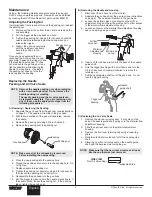
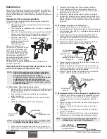
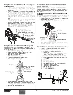
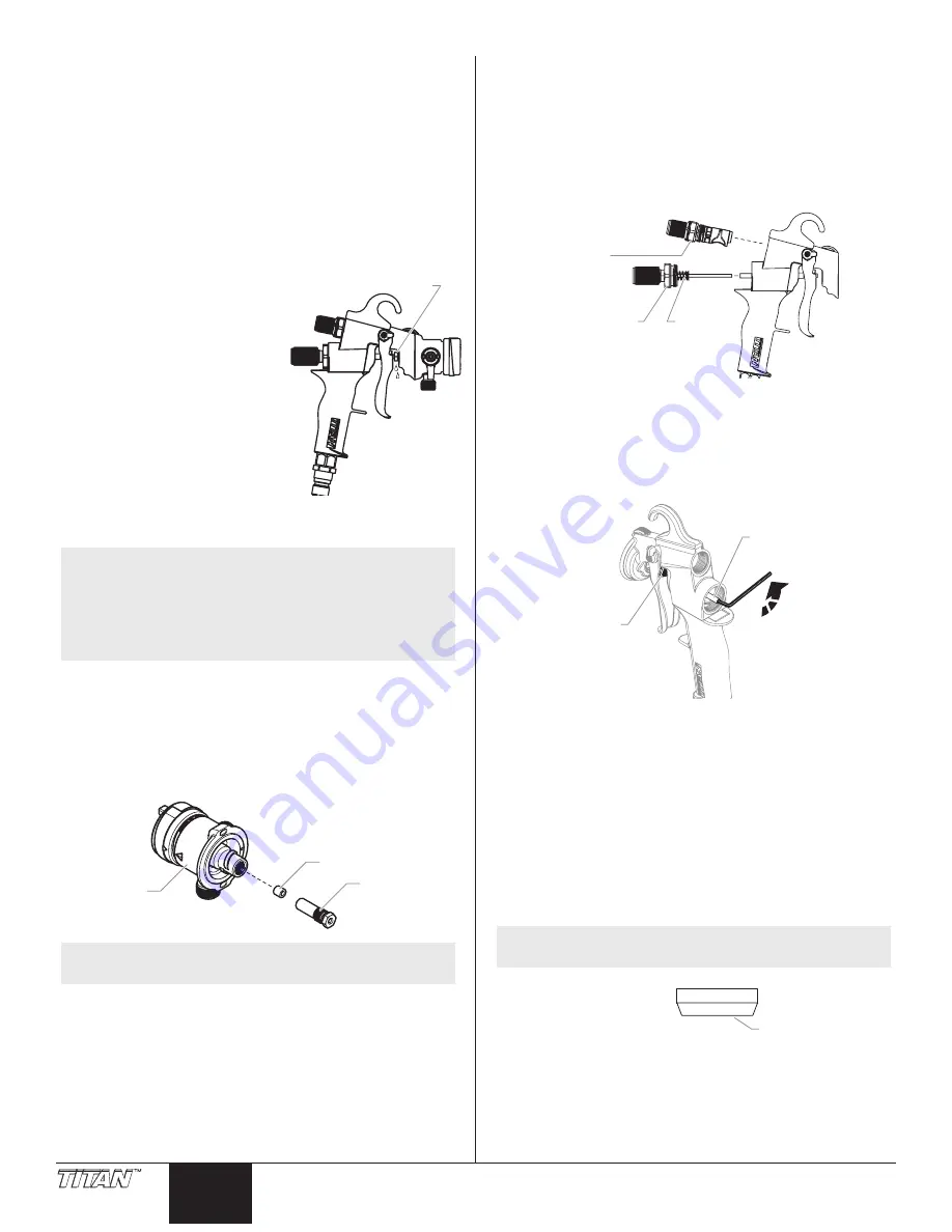
adjusting the Packing Nut

If material leaks from around or through the packing nut, readjust 

the packing nut.

  1.  Disconnect the air hose from the air inlet and remove the 

cup assembly.

  2.  Pull the trigger all the way back and hold.

  3.  Tighten the packing nut using a 3/8 inch wrench until the 

needle remains retracted inside the nozzle when you 

release the trigger.

Packing Nut 

  4.  Loosen the packing nut slowly 

until the needle moves freely 

back into position in the 

nozzle.

Once you have adjusted the nut, 

reconnect the air hose and the cup 

assembly.  Squeeze the trigger to see 

if the leaking has stopped.  If it has 

not, make sure the packing nut is as 

tight as possible, while allowing the 

needle to move freely.  If adjusting 

the packing nut does not stop the 

leak, replace the packing.

Replacing the Needle 

Packing and air valve Seals

 NOTE:  Remove the needle packing only when replacing 

with a new needle packing.  Do not remove the 

needle packing for cleaning.


  The needle packing and the air valve seals can 

be replaced separately.  If you are replacing only 

one of them, use the appropriate steps from the 

following procedures.

a) Removing / Replacing the Packing

  1.  Separate the gun head from the gun rear (see instructions 

on page 3).  The needle will remain in the gun head.

  2.  With the two sections of the gun still separated, remove 

the needle.

  3.  Remove the packing nut using a 3/8 inch wrench.

  4.  Remove the packing from the packing nut.

Gun head

Packing

Packing nut

 NOTE:  Make sure all of the old packing is removed 

before installing the new packing.

  5.  Place the new packing into the packing hole.

  6.  Thread the packing nut one turn into the packing hole.  Do 

not tighten.

  7.  Replace needle into packing nut.

  8.  Tighten the packing nut securely using a 3/8 inch wrench, 

then loosen the packing nut a quarter turn.

  9.  Reassemble the gun head into the gun body.

  10.  Pull the trigger to make certain the needle moves freely.  If 

the needle sticks, loosen the packing nut.  If the packing 

leaks, tighten the packing nut.

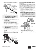
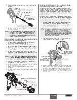
B) Removing the Needle and housing

  1.  Disconnect the air hose from the air inlet.

  2.  Separate the gun head from the gun rear (see instructions 

on page 3).  The needle will remain in the gun head.

  3.  Loosen the air flow valve nut and remove the air flow 

adjustment knob and the air flow valve nut to allow access 

to the material flow adjustment housing.

  4.  Loosen and remove the material flow adjustment housing,  

seal, and spring using a wrench.

Material

Adjustment

Housing

Seal and

spring

Air flow

 valve nut

  5.  Insert an 1/8 inch hex wrench into the back of the needle 

guide shaft.

  6.  Hold the trigger bushing with a small pliers and turn the 

1/8 inch hex wrench counterclockwise to remove the 

retaining nut.

  7.  Pull the needle guide shaft out of the gun body.  Do not 

lose the trigger bushing.

Needle

guide shaft

Trigger

bushing

c) Replacing the air valve Seals

  1.  Remove the old rear air valve seal.  It may stay on the 

end of the needle guide shaft spring or in the material flow 

adjustment housing.

  2.  Slide the new rear seal into the material adjustment 

housing.

  3.  Remove the front seal retaining clip using a snap-ring 

pliers.

  4.  Slide the old front air valve seal off of the needle guide 

shaft.

  5.  Place the new front air valve seal on the needle guide 

shaft with the beveled side facing the gun.

 NOTE:  Make sure that the new front air valve seal looks 

like the one that was just removed.

SIDE VIEW

Front Air Valve Seal

Beveled Side

Summary of Contents for 524027

Page 1: ...nstructions Please read and retain for reference Model Number 0524027 0524052 Model 0524027 CAPSpray Maxum Elite HVLP Spray Gun Owner s Manual Notice d utilisation Manual del Propietario Do not use this equipment before reading this manual Model 0524052 U S Patent No 5 655 714 D616 527 Other patents pending ...

Page 2: ...k to be sure it will provide the necessary protection Wear protective eyewear Wear protective clothing as required by coating manufacturer HAZARD Skin burn injury Heated parts can cause severe skin burn injury PREVENTION Quick disconnect fittings on the hose and spray gun become hot during use Avoid skin contact with quick disconnect fittings when they are hot Allow quick disconnect fittings to co...

Page 3: ... for each style of gun is included near the back of this manual Check valve Trigger Packing nut Air Inlet Material flow adj knob Air flow adj knob Trigger release Air cap ring Air cap Cup locking lever 1 Quart cup assembly Swivel tube lever Fluid inlet Lever Hook Note The hook on top of the gun body can be easily removed or reversed Slide the hook toward the rear of the gun to remove it Split Desi...

Page 4: ...y Pattern Size To change the spray pattern size without changing the spray pattern shape turn the air cap ring Smaller Pattern Bigger Pattern Air Cap Ring b a NOTE An ideal starting point is when the triangle mark on the air cap ring a is aligned with the triangle mark on the gun head b Turning the ring clockwise will make the pattern bigger Turning the ring counterclockwise will make the pattern ...

Page 5: ...he bridge corresponds with the position of the swivel tube Note The swivel tube lever is directly below the cup locking lever The cup locking lever secures the cup to the spray gun Swivel Tube Lever Cup Locking Lever Cleaning the Spray Gun It is very important to clean your HVLP spray gun thoroughly after each use 1 Empty the spray material from the cup 2 Pour a small amount of the appropriate sol...

Page 6: ...cking is removed before installing the new packing 5 Place the new packing into the packing hole 6 Thread the packing nut one turn into the packing hole Do not tighten 7 Replace needle into packing nut 8 Tighten the packing nut securely using a 3 8 inch wrench then loosen the packing nut a quarter turn 9 Reassemble the gun head into the gun body 10 Pull the trigger to make certain the needle moves...

Page 7: ...to the gun body see page 3 Gun head Gun body Gun body O ring Gun head seal Screws Gun body insert Replacing the Check Valve Retainer Valve Seal and Air Tube The check valve is a one way valve designed to allow air into the cup pressurizing the cup s contents Because it is a one way valve it prevents paint from seeping up the air tube into the air passages of the gun It also eliminates any delay in...

Page 8: ... into the lid 6 Place the spray gun onto the top of the cup Cup Gasket Bridge Lid Cup Locking Lever Swivel Lever 7 Turn the spray gun opposite the direction indicated by the arrows on the bridge until the pegs on the cup are in the notches of the bridge 8 Tighten the cup locking lever Using a Pressure Feed System To increase spray time between material refills your HVLP spray gun can be connected ...

Page 9: ... the retaining nut making sure the gun cup assembly stays in a level position The cup should end up in a vertical position when supported by the stand 6 Connect the air tube to the air tube fitting on the spray gun important The gun when converted to top feed will not stand on its own Make sure to use the stand when filling Do not lay the gun on its side when it is filled with material Do not hang...

Page 10: ...ctor set 6 complete 0524298 Projector set 7 complete 0276449 Air cap 2 0276452 Air cap 3 0276455 Air cap 4 0276458 Air cap 5 0276417 Air cap 6 0524401 Air cap 7 0276446 Nozzle 2 0276451 Nozzle 3 0276454 Nozzle 4 0276457 Nozzle 5 0276418 Nozzle 6 0524363 Nozzle 7 0524282A Needle assembly 2 0524283A Needle assembly 3 0524284A Needle assembly 4 0524285A Needle assembly 5 0524286A Needle assembly 6 05...

Page 11: ...projector set 1 Adjust the air cap properly so that paint flows freely through the cap 1 Reduce air pressure 2 Add unthinned paint 3 Move closer Troubleshooting Material Reduction Projector Set Chart Before spraying the material being used must be thinned with an appropriate solvent and the proper projector set must be installed It is always best to follow the material manufacturers recommendation...

Page 12: ...rmément aux directives du fabricant de revêtement Danger DANGER DE BRÛLURE Les pièces chauffées peuvent causer de graves brûlures cutanées Prévention Le plastique peut être une source d étincelles provoquées par l électricité statique Ne jamais utiliser une couverture en plastique pour fermer une zone d épandage ni utiliser des toiles de protection en plastique lors de la pulvérisation de matières...

Page 13: ...nte Écrou presse garniture Entrée d air Bouton de réglage du débit de produit Bouton de réglage du débit d air Déclenchement de la détente Bague de fixation du bouchon d air Bouchon d air Levier de blocage du godet Ensemble godet de 1 litre Levier de tube orientable Entrée du fluide Levier Crochet NotA Le crochet sur le haut du corps de pistolet peut être facilement retiré ou renversé Glisser le c...

Page 14: ...icale Position horizontale Aire de pulvérisation On peut changer l aire de pulvérisation sans en modifier la forme en faisant tourner la bague de fixation du bouchon d air Petite Grande Bague de fixation du bouchon d air b a NOTA Un point de départ idéal est lorsque le triangle sur la bague de réglage a est aligné avec le triangle sur la tête du pistolet b En tournant la bague vers la droite on ag...

Page 15: ...t La flèche sur le côté anti horaire de la couronne correspond à la position du levier d orientation Nota Le levier orientable est placé directement sous le levier de blocage du godet Celui ci assure la fixation du godet avec le pistolet Levier d orientation Levier de blocage du godet Nettoyage du pistolet Il est important de nettoyer entièrement le pistolet après chaque utilisation 1 Vider le god...

Page 16: ...e soit retirée avant de monter une nouvelle garniture 5 Placer une nouvelle garniture dans le trou de garniture 6 Faire tourner la garniture d un tour à l intérieur du trou Ne pas serrer 7 Remettre le pointeau dans l écrou presse garniture 8 Serrer fermement l écrou presse garniture au moyen d une clé de 3 8 de pouce puis desserrer l écrou presse garniture d un quart de tour 9 Remonter la tête du ...

Page 17: ...nt torique du corps du pistolet Joint de la tête du pistolet Vis Écrou du corps du pistolet Remplacement la retenue de clapet anti retour du joint de clapet et des tube d air Le clapet anti retour est un clapet unidirectionnel conçu pour admettre l air dans le godet et mettre le contenu de celui ci sous pression Comme c est un clapet unidirectionnel il empêche la peinture de s infiltrer dans le tu...

Page 18: ...mettre le pistolet sur le godet Joint d étanchéité de godet Couronne Couvercle Levier de blocage du godet Levier d orientation 7 Tourner le pistolet dans la direction opposée à celle indiquée par les flèches de la couronne jusqu à ce que les tenons du godet soient dans les encoches de la couronne 8 Serrer le levier de blocage du godet Utilisation d un système d alimentation sous pression De manièr...

Page 19: ...l écrou de retenue en veillant à ce que l ensemble du pistolet godet demeure horizontal Le godet devrait se trouver à la verticale lorsqu il est soutenu par le support 6 Raccorder le tube d air au raccord du tube d air sur le pistolet de vaporisation IMPORTANT Lorsqu il est converti à l alimentation par le haut le pistolet ne se tiendra pas debout tout seul Il faut utiliser un support pendant le r...

Page 20: ...8 Bouchon d air no 5 0276417 Bouchon d air no 6 0524401 Bouchon d air no 7 0276446 Buse no 2 0276451 Buse no 3 0276454 Buse no 4 0276457 Buse no 5 0276418 Buse no 6 0524363 Buse no 7 0524282A Pointeau no 2 0524283A Pointeau no 3 0524284A Pointeau no 4 0524285A Pointeau no 5 0524286A Pointeau no 6 0524287A Pointeau no 7 0508124 Couvercle à clipper 1 pinte 0524188 Ensemble accessoire pour embout 052...

Page 21: ...C La peinture refoule passé le clapet anti retour D Aire de pulvérisation irrégulière E Jet pulsé F Aire de pulvérisation plus dense au centre G Pistolet qui crachote H Accumulation de peinture sur le bouchon d air I Trop de pulvérisation hors cible Cause 1 De la peinture séchée obstrue la buse 2 Aucune pression d air dans le godet ou la bonbonne de peinture 3 Le clapet anti retour dans tube d air...

Page 22: ...nes de quemadura de la piel severas PREVENCIÓN Las conexiones de desconexión rápida de la manguera y la pistola de atomización se llegan a calentar mientras se usan Evite que la piel tenga contacto con las conexiones de desconexión rápida cuando se calienten Deje que las conexiones de desconexión rápida se enfríen antes de desconectar la pistola de atomización de la manguera PELIGRO INCENDIO O EXP...

Page 23: ...e Obturador de aire Palanca bioqueadora del depósito Conjunto del depósito de 1 cuarto Palanca del tubo giratorio Entrada de fluido Palanca Gancho NotA El gancho en la parte superior del cuerpo de la pistola puede ser extraído o invertido Para extraerlo deslice el gancho hacia la parte trasera de la pistola Diseño dividido La pistola pulverizadora HVLP tiene un diseño de pistola dividida que permi...

Page 24: ... del patrón de atomización Para cambiar el tamaño del patrón de atomización sin cambiar la forma del patrón gire el anillo del obturador del aire Anillo del obturador del aire Chico Grande b a NOTA Un buen punto de partida es cuando la marca triangular del anillo de regulación a está alineada con la marca triangular del cabezal de la pistola b Al girar el anillo en dirección de las manecillas del ...

Page 25: ...te en dirección opuesta a las manecillas del reloj La flecha del puente ubicada en el lado de la dirección opuesta a las manecillas del reloj coincide con la posición del tubo giratorio Nota La palanca del tubo giratorio está directamente debajo de la palanca bloqueadora del depósito La palanca bloqueadora del depósito sujeta el depósito a la pistola atomizadora Palanca giratoria Palanca bloqueado...

Page 26: ...mpaque usado antes de poner el empaque nuevo 5 Ponga el empaque nuevo en la ranura del empaque 6 Gire la tuerca de empaque una vuelta hacia el interior de la ranura del empaque No la apriete 7 Reemplace la aguja en la tuerca del prensaestopas 8 Apriete firmemente la tuerca de empaque usando una llave de 3 8 de pulgada luego afloje la tuerca de empaque un cuarto de vuelta 9 Vuelva a instalar la cab...

Page 27: ...stola Cuerpo de la pistola Junta tórica del cuerpo de la pistola Junta del cabezal de la pistola Tornillos Inserto del cuerpo de la pistola Cómo cambiar el retén de la válvula de retención el sello de la válvula y le tubo de aire La válvula de retención es una válvula de un sentido para permitir que el aire pase al depósito presurizando asi el material contenido en el depósito Debido a que la válv...

Page 28: ... trabadora del depósito Palanca del tubo giratorio 7 Gire la pistola atomizadora en dirección opuesta a la indicada por las flechas ubicadas en el puente hasta que las espigas del depósito estén en las ranuras del puente 8 Apriete la manija trabadora del depósito Cómo utilizar un sistema de alimentación a presión Para aumentar el tiempo de atomizado su pistola atomizadora HVLP se puede conectar a ...

Page 29: ...la pistola permanecen en una posición nivelada El depósito debe permanecer en una posición vertical cuando esté sobre el acople 6 Conecte el tubo de aire a la conexión del tubo de aire de la pistola pulverizadora IMPORTANTE La pistola no se mantendrá en posición vertical por sí sola cuando se haya convertido al modo de alimentación por la parte superior Utilice algún medio de soporte durante la fa...

Page 30: ... aire 2 0276452 Obturador del aire 3 0276455 Obturador del aire 4 0276458 Obturador del aire 5 0276417 Obturador del aire 6 0524410 Obturador del aire 7 0276446 Boquilla 2 0276451 Boquilla 3 0276454 Boquilla 4 0276457 Boquilla 5 0276418 Boquilla 6 0524363 Boquilla 7 0524282A Conjunto de aguja 2 0524283A Conjunto de aguja 3 0524284A Conjunto de aguja 4 0524285A Conjunto de aguja 5 0524286A Conjunto...

Page 31: ... laca 3 Problema A Flujo de pintura pequeño o no flujo B La pintura se fuga C La pintura regresa y atraviesa la válvula de retención D Patrón de atomización deficiente E Atomización trepidante F El patrón es denso en el centro G La pistola escupe pintura H Acumulación de pintura en el obturador del aire I Se atomiza demasiado Causa 1 Pintura seca que bloquea la boquilla de fluido 2 No hay presión ...

Page 32: ...7 40 11 12 13 14 18 19 23 20 24 25 26 51 21 22 15 41 42 43 44 45 46 47 48 49 50 16 17 27 29 30 38 39 28 for bleeder conversion Pour transformer le pistolet en dispositif purgeur para conversión con purgador Parts List Liste de pièces Lista de piezas Gun Assembly Ensemble de pistolet Ensamblaje de pistola ...

Page 33: ... Palanca 2 22 0524698 Seal Joint Sello 2 23 0524697 Trigger pin Goupilles de détente Pasador del gatillo 1 24 0524498A Handle tube Tube de poignée Tubo del asa 1 25 0524497 Handle tube nut Écrou de tube de poignée Tuerca del tubo del asa 1 26 0275481 Quick disconnect fitting Raccord rapide Adaptador de desconexión rápida 1 27 0524495 Gun hook Agrafe du pistolet Gancho de la pistola 1 28 0524504 Gu...

Page 34: ... Couronee Puente 1 5 0277467 Cup locking lever Levier de blocage du godet Palanca bloqueadora del depósito 1 6 0277460 Lid Couvercle Tapa 1 7 9871049 O ring Joint torique Junta de anillo 1 8 9805206 Screw Vis Tornillo 1 9 0277448 Swivel lever Levier d orientation Palanca giratoria 1 10 0277449 Guide Guide Guía 1 11 0277178 Tube Tube Tubo 1 12 0277495 Cup gasket Joint d étanchéité du godet Empaque ...

Page 35: ...daptador de 90º 1 3 0524149A Pressure tube Tube de pression Tubo de presión 2 4 0276248 Check valve assembly Ensemble clapet anti retour Conjunto de válvula de retención 1 5 0524144A Fitting Raccord Conector 1 6 0529335 Screw Vis Tornillo 1 7 0529334 Washer Rondelle Arandela 2 8 0529336 Nut Écrou Tuerca 1 9 0529333A Stand Support Soporte 1 0524045 Top feed cup assembly includes items 1 9 Ensemble ...

Page 36: ... ce dernier 3 La présente garantie ne couvre pas les défauts ou les dommages découlant de l abrasion de la corrosion de l usage abusif de l emploi incorrect de négligence d accidents de l usure normale d une installation fautive ou d une intervention non autorisée susceptible de nuire au fonctionnement normal de l équipement Limitation des recours Titan NE PEUT EN AUCUN CAS ÊTRE TENUE RESPONSABLE ...

Reviews: