English
English
© Titan Tool Inc. All rights reserved.
11
resetting the Pressure Switch Timing
NOTE: It is recommended that the following procedure be
performed by a Titan authorized Service center.
NOTE: The components of the pressure switch must be
properly reassembled and adjusted in order for the
pump to operate at the correct maximum pressure.
Perform this procedure using pressure gauge P/N 0508239.
1. Make sure the knob bottom (1) is installed in the pressure
switch (2).
2. Viewing from the top, turn the knob bottom (1) counter-
clockwise as far as the teeth inside the pressure switch will allow.
1
3
2
NOTE: If the stop (3) on the pressure switch prevents the
knob bottom from continuing to turn, remove the
knob bottom, re-orient it on the teeth and continue
to turn it counterclockwise until it stops.
3. Re-orient the knob tab against the pressure switch tab stop.
4. Replace the front cover and secure with the three screws.
5. Replace the pressure control knob into the knob bottom but
do not secure with the screw. Turn the knob fully clockwise to
maximum.
6. Connect the pressure gauge to the outlet fitting.
7. Connect a high-pressure hose and gun to the pressure gauge.
8. Using water as a media, follow the steps in the “Painting”
section. It is not necessary to attach a spray tip to the gun.
Leave the pressure set to maximum.
9. The sprayer should now be pressurized at maximum pressure.
The pressure gauge should be reading between 2800-3000
PSI.
10. If the pressure reading is below or above this reading, the
set screw down inside the pressure switch will have to be
adjusted. Adjust it per the guidelines below using a long hex
wrench.
a. If the pressure reading is below 2800 PSI, turn the set screw
counterclockwise until the pressure gauge reads between 2800-
3000 PSI.
b. If the pressure reading is above 3000 PSI, relieve pressure by
turning the PRIME/SPRAY knob to PRIME. While the sprayer is
circulating, turn the set screw clockwise slightly and then turn
the PRIME/SPRAY knob to SPRAY. Repeat this until the pressure
reading decreases to a range of 2800-3000 PSI.
11. When the pressure gauge reads between 2800-3000 PSI, the
pressure control knob is now set. Secure the pressure control
knob with the pressure control knob screw.
replacing the circuit Board
NOTE: It is recommended that the following procedure be
performed by a Titan authorized Service center.
Perform this procedure using Circuit Board Kit P/N 0532208A.
1. Perform the Pressure Relief Procedure and unplug the sprayer.
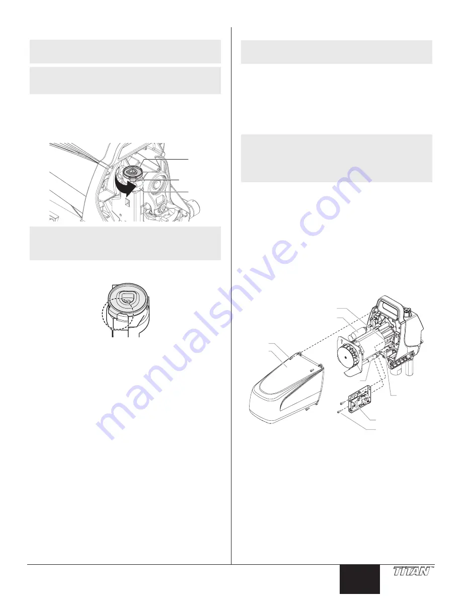
2. Loosen and remove the four motor cover screws (1). Remove
the motor cover (2).
3. Disconnect the red and black wires that connect the circuit
board (3) to the motor assembly (4).
4. Disconnect the white wires that connect the circuit board to
the pressure switch.
NOTE: The pressure switch will not be visible as it is
located on the other side of the motor housing. The
white wires will be visible through an opening in
the housing (5). If the wire connector is not visible,
gently pull the wires through the opening until the
connector is accessible.
5. Disconnect the black wire that connects the circuit board to
the circuit breaker (6).
6. Disconnect the white wire that connects the circuit board to
the power switch (7).
7. Loosen and remove the two circuit board screws (8). Remove
the circuit board (3).
8. Install the new circuit board (3) and secure with the two circuit
board screws (8).
9. Reconnect the wires that were disconnected in steps 3-6
(refer to the electrical schematic in the Parts List section of this
manual).
10. Slide the motor cover over the motor. Secure the motor cover
with the four motor cover screws.
1
4
7
5
3
8
6
2


