background image

English

English

© Titan Tool Inc.  All rights reserved. 

5

Setup

Perform the following procedure before plugging in the power cord 

of an electric unit.
  1.  Ensure that the siphon tube and the return hose are attached 

and secure.

  2.  Using a wrench, attach a minimum of 50’ of 1/4” airless spray 

hose to the outlet fitting on the sprayer.  Tighten securely.

  3.  Attach an airless spray gun to the spray hose.  Using two 

wrenches (one on the gun and one on the hose), tighten 

securely.

  NOTE:  Do not attach the tip to the spray gun yet.  remove 

the tip if it is already attached.

make sure all airless hoses and spray guns are 

electrically grounded and rated at or above the 

maximum operating pressure range of the airless 

sprayer. 

  4.  Make sure the pressure control knob is turned fully 

counterclockwise to its lowest pressure setting.

  5.  Make sure the ON/OFF switch is in its OFF position.
  6.  Fill the oil cup with approximately one tablespoon of Piston 

Lube™ (see “Accessories” section, page 54).

ImPOrTaNT:  Never operate unit for more than ten seconds 

without fluid.  Operating this unit without fluid will cause 

unnecessary wear to the packings.
  7.  Make sure the electrical service is 120V, 15 amp minimum.
  8.  Plug the power cord into a properly grounded outlet at least 

25’ from the spray area.

ImPOrTaNT:  always use a minimum 12 gauge, three-wire 

extension cord with a grounded plug.  Never remove the third 

prong or use an adapter.

Preparing a New Sprayer

If this sprayer is new, it is shipped with test fluid in the fluid section to 

prevent corrosion during shipment and storage.  This fluid must be 

thoroughly cleaned out of the system with mineral spirits before you 

begin spraying.
ImPOrTaNT:  always keep the trigger lock on the spray gun in 

the locked position while preparing the system.
  1.  Place the siphon tube into a container of mineral spirits.
  2.  Place the return hose into a metal waste container.
  3.  Set the pressure to minimum by turning the pressure control 

knob fully counterclockwise.

  4.  Move the PRIME/SPRAY valve down to the PRIME position.
  5.  Turn on the sprayer by moving the ON/OFF switch to the ON 

position.

  6.  Allow the sprayer to run for 15–30 seconds to flush the 

test fluid out through the return hose and into the waste 

container.

  7.  Turn off the sprayer by moving the ON/OFF switch to the OFF 

position.

Preparing to Paint

Before painting, it is important to make sure that the fluid in the 

system is compatible with the paint that is going to be used.

  NOTE:  Incompatible fluids and paint may cause the valves 

to become stuck closed, which would require 

disassembly and cleaning of the sprayer’s fluid 

section.

ImPOrTaNT:  always keep the trigger lock on the spray gun in 

the locked position while preparing the system.
  1.  Place the siphon tube into a container of the appropriate 

solvent.  Examples of the appropriate solvent are water for 

latex paint or mineral spirits for oil-based paints.

  2.  Place the return hose into a metal waste container.
  3.  Set the pressure to minimum by turning the pressure control 

knob fully counterclockwise.

  4.  Move the PRIME/SPRAY valve down to the PRIME position.

  NOTE:  Hold the return hose in the waste container when 

moving the PrImE/SPray valve to PrImE in case the 

sprayer is pressurized.

  5.  Turn on the sprayer by moving the ON/OFF switch to the ON 

position. 

  6.  Allow the sprayer to run for 15–30 seconds to flush the old 

solvent out through the return hose and into the metal waste 

container.

  7.  Turn off the sprayer by moving the ON/OFF switch to the OFF 

position.

  NOTE:  make sure that the spray gun does not have a tip or 

tip guard installed.

  8.  Move the PRIME/SPRAY valve up to the SPRAY position.
  9.  Turn on the sprayer.
  10.  Unlock the gun by turning the gun trigger lock to the 

unlocked position.

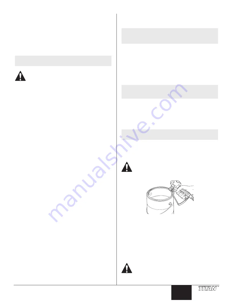
Ground the gun by holding it against the edge of the 

metal container while flushing.  Failure to do so may 

lead to a static electric discharge, which may cause a 

fire.

  11.  Trigger the gun into the metal waste container until the old 

solvent is gone and fresh solvent is coming out of the gun.

  12.  Lock the gun by turning the gun trigger lock to the locked 

position.

  13.  Set down the gun and increase the pressure by turning the 

pressure control knob slowly clockwise.

  14.  Check the entire system for leaks.  If leaks occur, follow the 

“Pressure Relief Procedure” in this manual before tightening 

any fittings or hoses.

  15.  Follow the “Pressure Relief Procedure” in this manual before 

changing from solvent to paint.

Be sure to follow the “Pressure relief Procedure” when 

shutting down the sprayer for any purpose, including 

servicing or adjusting any part of the spray system, 

changing or cleaning spray tips, or preparing for 

cleanup.

Summary of Contents for 532000

Page 1: ...ons Please read and retain for reference Owner s Manual Notice d utilisation Manual del Propietario Do not use this equipment before reading this manual Register your product online at www titantool com Serial Number _ _ _ _ _ _ _ _ _ _ See page 53 for location IMPACT 400 Airless Sprayer Model 0532001 Model 0532000 ...

Page 2: ...ified by the manufacturer Verify that all containers and collection systems are grounded to prevent static discharge Connect to a grounded outlet and use grounded extension cords electric models only Do not use a 3 to 2 adapter Do not use a paint or solvent containing halogenated hydrocarbons Such as chlorine bleach mildewcide methylene chloride and trichloroethane They are not compatible with alu...

Page 3: ...ing and balance at all times Stay alert and watch what you are doing Do not operate the unit when fatigued or under the influence of drugs or alcohol Do not kink or over bend the hose Airless hose can develop leaks from wear kinking and abuse A leak can inject material into the skin Do not expose the hose to temperatures or pressures in excess of those specified by manufacturer Do not use the hose...

Page 4: ...hroud are designed to keep the motor from getting excessively hot during operation Make sure the vents in the bottom and rear of the motor shroud are not covered or obstructed Locking the Spray Gun 1 To lock the trigger rotate the trigger lock forward until it stops 2 To unlock the trigger rotate the trigger lock backwards until it is vertical Trigger locked gun will not spray Trigger unlocked gun...

Page 5: ... Turn off the sprayer by moving the ON OFF switch to the OFF position Preparing to Paint Before painting it is important to make sure that the fluid in the system is compatible with the paint that is going to be used NOTE Incompatible fluids and paint may cause the valves to become stuck closed which would require disassembly and cleaning of the sprayer s fluid section Important Always keep the tr...

Page 6: ...n unless the tip is in either the spray or the unclog position Always engage the gun trigger lock before removing replacing or cleaning tip 16 Turn on the sprayer 17 Increase the pressure by turning the pressure control knob slowly clockwise and test the spray pattern on a piece of cardboard Adjust the pressure control knob until the spray from the gun is completely atomized Try to keep the pressu...

Page 7: ...e gun trigger lock 6 Trigger the spray gun to bleed air out of the hose Good spray pattern Paint tailing pattern 7 When paint reaches the spray tip spray a test area to check the spray pattern 8 Use the lowest pressure setting necessary to get a good spray pattern If the pressure is set too low tailing will appear or the paint will spatter out in gobs rather than in a fine spray NOTE Turning the p...

Page 8: ... 7 Turn on the sprayer by moving the ON OFF switch to the ON position 8 Allow the solvent to circulate through the unit and flush the paint out of the return hose into the metal waste container 9 Turn off the sprayer by moving the ON OFF switch to the OFF position 10 Move the PRIME SPRAY valve up to its SPRAY position 11 Turn on the sprayer Ground the gun by holding it against the edge of the meta...

Page 9: ...on the type of cleaning solvent Always contact the supplier of solvents for recommendations 4 If you have any further questions concerning your Titan Airless Sprayer call Titan Customer Service 1 800 526 5362 Fax 1 800 528 4826 Replacing the Motor NOTE It is recommended that the following procedure be performed by a Titan Authorized Service Center 1 Perform the Pressure Relief Procedure and unplug...

Page 10: ...djustment or there is paint leakage from the front of the sprayer the pressure switch and or transducer may need to be replaced 1 Perform the Pressure Relief Procedure and unplug the sprayer 2 Remove the screw 1 that secures the pressure control knob 2 to the bottom of the pressure control knob 3 Remove the knob 2 3 Loosen and remove the three front cover screws 4 Remove the front cover 5 4 Remove...

Page 11: ...rclockwise until the pressure gauge reads between 2800 3000 PSI b If the pressure reading is above 3000 PSI relieve pressure by turning the PRIME SPRAY knob to PRIME While the sprayer is circulating turn the set screw clockwise slightly and then turn the PRIME SPRAY knob to SPRAY Repeat this until the pressure reading decreases to a range of 2800 3000 PSI 11 When the pressure gauge reads between 2...

Page 12: ...00 897 Install with o ring tool 700 890 8 Replacing the Filters Pump Filter 1 Loosen and remove the filter housing 1 2 Turning clockwise unscrew the filter 2 from the pump manifold 3 NOTE Left handed threads require turning the filter clockwise to remove 3 Make sure the filter seal 4 is in position 4 Turning counterclockwise screw the new or cleaned filter into the pump manifold 5 Slide the filter...

Page 13: ... section allows access to the foot valve and seat as well as the outlet valve and seat without completely disassembling the fluid section It is possible that the valves may not seat properly because of debris stuck in the foot valve seat or outlet valve seat Use the following instructions to clean the valves and replace the seats Servicing the Inlet Valve 1 3 4 6 5 7 2 8 1 Using a wrench loosen an...

Page 14: ...Insert the lower packing partially into the bottom of the pump block so that the beveled edge 24 of the packing faces up 5 Thread the inlet valve housing 22 back into the bottom of the pump housing by hand to drive the lower packing into place Once tightened as far as it will go unthread and remove again 6 Place the grey insertion tool over the top of the piston assembly 18 Coat the piston guide t...

Page 15: ...2 Check the siphon tube suction set connection and tighten or re tape the connection with PTFE tape 3 Remove the pump filter element and clean Remove the inlet screen and clean 4 Remove the siphon tube suction set and clean 1 Replace the spray tip following the instructions that came with the spray gun 2 Replace the spray tip with a tip that has a smaller orifice following the instructions that ca...

Page 16: ...lisez pas d adaptateur 3 à 2 N utilisez pas de peinture ou de solvant contenant du halon par exemple le chlore les agents antimoisissure à l eau de Javel le chlorure de méthylène et le trichloroéthane Ils ne sont pas compatibles avec l aluminium Contactez le fournisseur de revêtements pour connaître la compatibilité du matériau avec l aluminium La zone de pulvérisation doit toujours être bien aéré...

Page 17: ... les deux pieds pour toujours conserver l équilibre Soyez attentif et regardez ce que vous faites N utilisez pas l appareil quand vous êtes fatigué ou sous l influence de drogues ou d alcool Ne faites pas de nœuds avec le tuyau et ne le tordez pas trop Le tuyau à vide peut présenter des fuites suite à l usure les nœuds ou les mauvais traitements Une fuite risque d injecter du produit dans la peau ...

Page 18: ... sont conçus pour empêcher le moteur de devenir excessivement chaud pendant son utilisation Assurez vous que les évents au bas et à l arrière du capot du moteur ne sont pas recouverts ou obstrués Verrouillage du pistolet de pulvérisation 1 Pour verrouiller le pistolet tournez le verrou de détente vers l avant et légèrement vers le bas jusqu à la butée 2 Pour déverrouiller le pistolet tourner le ve...

Page 19: ...r le flexible de retour jusqu au contenant de purge 7 Arrêter l appareil en mettant le commutateur à la position OFF Préparation avant de peindre Avant de peindre il est important de s assurer que le liquide dans l appareil est compatible avec le produit à utiliser NOTA L incompatibilité liquide produit peut provoquer le blocage des soupapes ce qui entraînerait le besoin de démonter et de nettoyer...

Page 20: ...ans avoir mis l embout en position de vaporisation ou de désobstruction Toujours enclencher le verrou de détente avant de retirer de remplacer ou de nettoyer l embout 16 Mettre l appareil en marche 17 Augmenter la pression en tournant lentement le bouton de régulation vers la droite jusqu à la zone verte puis effectuer un essais sur un morceau de carton en examinant le jet résultant Régler la pres...

Page 21: ... Appuyer sur la détente pour évacuer l air du flexible Bonne répartition de la pulvérisation Traînées de peinture 7 Quand la peinture atteint l embout effectuer un essai de vaporisation en vue de régler le jet en fonction du travail à effectuer 8 Régler la pression au niveau le plus bas qui permette d obtenir le jet désiré Si elle est trop basse le jet produira des traînées ou crachera des grumeau...

Page 22: ...as où le pulvérisateur est sous pression 7 Mettre l appareil en marche en mettant le commutateur à la position ON 8 Laisser le solvant circuler dans l appareil pour évacuer le produit de peinture par le flexible de retour jusqu au contenant de purge 9 Arrêter l appareil en mettant le commutateur à la position OFF 10 Soulever la soupape prime spray à la position SPRAY 11 Mettre l appareil en marche...

Page 23: ...protection lorsqu on procède à la maintenance D autres dispositifs protecteurs pourraient être requis selon le type de solvant utilisé on doit toujours communiquer avec le fabricant de ce dernier pour obtenir ses recommandations à cet effet 4 Pour toute autre question relative à ce vaporisateur à dépression il suffit de communiquer avec Titan Service à la clientèle 1 800 526 5362 Télécopieur 1 800...

Page 24: ...erd tout ajustement de pression ou s il y a une fuite de l avant du pulvérisateur le pressostat et ou le transducteur pourraient devoir être remplacés 1 Suivre la Procédure de décompression et débrancher l appareil 2 Retirez la vis 1 qui fixe le bouton de commande de pression 2 au bas du bouton de commande de pression 3 Retirez le bouton 2 3 Desserrer et retirer les quatre vis 1 du carter de moteu...

Page 25: ... à 193 bar 2 800 PSI tournez la vis de réglage dans le sens contraire aux aiguilles d une montre jusqu à ce que le manomètre indique entre 193 et 207 bar 2 800 et 3 000 PSI b Si la pression est supérieure à 207 bar 3 000 PSI réduisez la pression en tournant le bouton PRIME SPRAY à PRIME Pendant que le pulvérisateur circule tournez la vis de réglage dans le sens des aiguilles d une montre légèremen...

Page 26: ...l approprié 700 890 8 Remplacement des filtres Filtre de pompe 1 Dégager et retirer le logement du filtre 1 2 En tournant vers la droite dévisser le filtre 2 du logement du pompe 3 NOTA Le filetage à gauche requiert qu on tourne vers la droite pour dévisser 3 S assurer que le joint de la filtre 4 soit bien placé 4 En tournant vers la gauche visser le filtre nettoyé ou de rechange sur le logement d...

Page 27: ... Maintenance des soupapes La conception de la section des liquides du vaporisateur fait en sorte qu on peut accéder aux soupapes de retenue et de sortie de même qu à leur siège respectif sans avoir à démonter toute la section Il arrive que ces soupapes soient mal assises à cause de débris accumulés en suivant les directives ci dessous on peut les nettoyer et remplacer leur siège Maintenance de sou...

Page 28: ...rniture d étanchéité inférieure partiellement dans le bas du groupe de pompage de façon à ce que le bord biseauté 24 de la garniture fasse face vers le haut 5 Faites passer le boîtier de la soupape d admission 22 jusqu au bas du boîtier de la pompe à la main pour mettre en place la garniture d étanchéité inférieure Une fois le tout serré autant que possible dévissez et retirez de nouveau 6 Glisser...

Page 29: ...lles d une montre en position prime 2 Vérifier le branchement du flexible du siphon d aspiration et serrer ou recoller le raccord avec du ruban en PTFE 3 Démonter le filtre de la pompe et le nettoyer Démonter le filtre d entrée et le nettoyer 4 Démonter le flexible du siphon d aspiration et le nettoyer 1 Remplacer l embout d aspiration selon les consignes qui accompagnent le pistolet de vaporisati...

Page 30: ...tierra especificadas por el fabricante Compruebe que todos los recipientes y sistemas de recogida están conectados a tierra para evitar descargas eléctricas Conecte a una salida con toma a tierra y utilice cables alargadores puestos a tierra No utilice un adaptador de 3 a 2 No utilice pintura o disolvente que contenga hidrocarburos halogenados como cloro fungicida blanqueador cloruro de metileno y...

Page 31: ...o se encuentra bajo la influencia del alcohol o de las drogas No retuerza ni doble la manguera en exceso En la manguera airless pueden aparecer fugas a causa del desgaste de retorcimientos o de un mal uso Una fuga puede inyectar material en la piel No exponga la manguera a temperaturas o presiones que superen las especificadas por el fabricante No utilice la manguera como elemento de fuerza para t...

Page 32: ...están diseñados para evitar que el motor se caliente demasiado durante el funcionamiento Asegúrese de que los ductos de ventilación en la parte inferior y posterior de la cubierta del motor no estén cubiertos ni obstruidos Bloquear la pistola 1 Para bloquear la pistola gire el seguro del gatillo hacia adelante y levemente hacia abajo hasta que se detenga 2 Para desbloquear la pistola gire el segur...

Page 33: ...de desecho 7 Apague la unidad moviendo el interruptor de ON OFF ENCENDIDO APAGADO a la posición OFF APAGADO Preparación para pintar Antes de pintar es importante revisar que el líquido del sistema sea compatible con la pintura que va a utilizar NOTA Los líquidos y pinturas incompatibles pueden causar que se atasquen cerradas las válvulas lo cual puede necesitar que se desmonte y limpie la sección ...

Page 34: ...illo de la pistola a menos que la punta esté en la posición de rociado o desatasco Siempre coloque el seguro del gatillo de la pistola antes de retirar reemplazar o limpiar la punta 16 Encienda la unidad 17 Aumente la presión girando la perilla de control de presión lentamente en el sentido horario hacia la zona verde y pruebe el patrón de rociado en un trozo de cartón Ajuste la perilla de control...

Page 35: ...durecerá a medida que la pintura comience a fluir 5 Libere el seguro del gatillo de la pistola 6 Apriete el gatillo de la pistola rociadora para purgar el aire de la manguera Patrón de atomización correcto Patron de desvanecimiento de pintura 7 Cuando la pintura llegue a la boquilla rocíe un área de prueba para examinar el patrón de rociado 8 Use el ajuste de presión más bajo necesario para obtene...

Page 36: ...unidad moviendo el interruptor de ON OFF a la posición ON 8 Deje circular el solvente a través de la unidad y purgue la pintura de la manguera de retorno hacia el recipiente metálico para desecho 9 Apague la unidad moviendo el interruptor de ON OFF a la posición OFF 10 Mueva hacia arriba la válvula PRIME SPRAY a su posición SPRAY 11 Encienda la unidad Conecte a tierra la pistola apoyándola contra ...

Page 37: ...del tipo de solvente de limpieza Siempre pida recomendaciones al proveedor de solventes 4 Si tiene otras preguntas referentes al rociador Titan llame a Titan Servicio al cliente 1 800 526 5362 Fax 1 800 528 4826 Reemplazo del motor NOTA Se recomienda realizar el siguiente procedimiento en un Centro de servicio técnico autorizado de Titan 1 Siga el Procedimiento de alivio de presión y desenchufe la...

Page 38: ... bien si existe una fuga de pintura por la parte delantera del pulverizador es posible que deba reemplazar el presostato o el transductor 1 Siga el Procedimiento de alivio de presión y desenchufe la unidad 2 Retire el tornillo 1 que fija la perilla de control de presión 2 a la parte inferior de la perilla de control de presión 3 Retire la perilla 2 3 Suelte y retire los tres tornillos 4 de la cubi...

Page 39: ...erda hasta que el manómetro indique entre 193 y 207 bar b SI la lectura de presión es superior a 207 bar gire la perilla PRIME SPRAY cebar pulverizar a PRIME para aliviar la presión Mientras el pulverizador está circulando gire el tornillo de ajuste levemente hacia la derecha y luego gire la perilla PRIME SPRAY a SPRAY Repita esto hasta que la lectura de presión disminuya entre 193 y 207 bar 11 La...

Page 40: ...ara juntas tóricas 700 890 8 Reemplazo de los filtros Filtro de la bomba 1 Suelte y retire la caja del filtro 1 2 Girando en el sentido horario atornille el filtro 2 del bloque de la bomba 3 NOTA Con los roscados hacia la izquierda se debe girar el filtro en el sentido horario para retirarlo 3 Revise que el sello del filtro 4 esté en posición 4 Girando en el sentido antihorario atornille el filtro...

Page 41: ...cción de líquido permite el acceso a la válvula de entrada y su asiento así como también a la válvula de salida y su asiento sin necesidad de desmontar completamente la sección de líquido Es posible que las válvulas no se asienten correctamente debido a residuos atrapados en el asiento de la válvula de pie o en la válvula de salida Use las instrucciones a continuación para limpiar las válvulas e r...

Page 42: ...la parte inferior del bloque de la bomba de manera que el lado biselado 24 de la empaquetadura esté orientado hacia arriba 5 Enrosque la carcasa de la válvula de entrada 22 de vuelta en la parte inferior de la carcasa de la bomba con la mano para dirigir la empaquetadura inferior a su lugar Una vez apretada lo más que se pueda desenrosque y retírela nuevamente 6 Coloque la herramienta gris de inse...

Page 43: ...ruebe la conexión del tubo de sifón juego de succión y apriete o vuelva a asegurar la conexión con cinta PTFE 3 Quite el elemento del filtro de bomba y límpielo Quite la malla de entrada y límpiela 4 Quite el tubo de sifón juego de succión y límpielo 1 Quite la punta rociadora siguiendo las instrucciones suministradas con la pistola rociadora 2 Reemplace la punta rociadora por una punta que tenga ...

Page 44: ...44 Titan Tool Inc All rights reserved 5 1 2 1 0532000 0532001 8 12 9 4 3 3 11 10 7 6 Parts List Liste de pièces Lista de piezas Main Assembly Vue d ensemble Ensamblaje principal ...

Page 45: ...ión 9 0551556 Return tube Tube de retour Tubo de retorno 10 0327226 Return tube clamp Agrafe de tube de retour Sujetador del tubo de retorno 11 730 334 Clip Agrafe Sujetador 12 710 046 Inlet filter Filtre d entrée Filtro de entrada See separate listing Voir la liste distincte Consulte la lista separada Part No Nº de piéce Pieza No English Description Français Description Español Descripción 1 0532...

Page 46: ... Todo trabajo eléctrico debe realizarlo un centro de servicio autorizado NOTA Tous les travaux d électricité doivent être effectués par le personnel d un centre de service autorisé NOTE All electrical work should be performed by an authorized service center 400 S Stand model Modèle de support Modelo de soporte 400 C Cart model Modèle de chariot Modelo de carrito ...

Page 47: ...et Joint d étanchéité Empaquetadura 11 800 925 800 925 Bypass valve assembly Assemblage de clapet de dérivation Conjunto de válvula de derivación 12 700 252 700 252 Cam base Base à came Base de leva 13 700 759 700 759 Groove pin Goupille Pasador de surco 14 700 697 700 697 Valve handle Manette de soupape Mango de la válvula 15 0532206 0532206 Circuit breaker assembly 12A Assemblage du disjoncteur ...

Page 48: ... supérieur Tuerca superior 7 0532914 0532914 Upper packing Tampon graisseur supérieur Empaquetadura superior 8 0532222A 0532222A Front cover Ensemble de couvercle Ensamblaje de cubierta frontal 1 2 3 4 5 10 8 24 23 22 21 16 17 18 25 19 20 26 27 28 29 30 31 32 11 12 13 14 15 9 6 7 37 33 34 35 36 Optional Facultatif Opciónal Drive Assembly II Boîte d engrenages II Ensamblaje de la caja de engranajes...

Page 49: ...lvula de pie 31 762 058 762 058 O ring PTFE Joint torique PTFE Junta tórica PTFE 32 704 054 730 511 Inlet valve housing Soupape de retenue Válvula de pie Optional Facultatif Opciónal 33 805 351A 805 351A Inlet valve Soupape de retenue Válvula de pie 34 800 332 800 332 O ring Joint torique Junta tórica 35 805 350 805 350 Pusher assembly clip Agrafe de ensemble de poussior Sujetador ensamblaje de vá...

Page 50: ...2 856 002 Washer 6 Rondelle 6 Arandela 6 3 856 921 Screw 2 Vis 2 Tornillo 2 4 0551555 Screw 4 Vis 4 Tornillo 4 5 0507655 Cord wrap 2 Fixation câble d alimentation 2 Soporte para envolver el cable eléctrico 2 6 Cart weldment Châssis de base Carro 7 0278373 Wheel 2 Roue 2 Rueda 2 8 0294534 Spacer 4 Espaceur de roue 4 Separador de rueda 4 9 9890104 Axle cap 2 Chapeau de roue 92 Tapa de rueda 2 10 029...

Page 51: ...oint torique pour solvants chauds facultatif Junta tórica para solventes calientes opcional 6 9822526 Retaining clip Agrafe de retenue Sujetador de retención 7 9850638 Tie wrap Cord d amarrage Amarra 8 0327226 Return tube clamp Agrafe de tube de retour Sujetador de tubo de retorno 9 193 200 Return tube fitting Raccord de tube de retour Conector de tubo de retorno Labels Étiquettes Etiquetas Part N...

Page 52: ...ambre 0532226 ON OFF switch Interrupteur Interruptor 9850936 Circuit breaker Disjoncteur Disyuntor Motor Moteur Motor 0532206A Motor assembly Ensemble de moteur Conjunto del motor 0532812 Green Vert Verde Red Rouge Rojo Red Rouge Rojo Red Rouge Rojo Black Noir Negro Black Noir Negro White Blanc Blanco Black Noir Negro Black Noir Negro White Blanc Blanco White Blanc Blanco White Blanc Blanco NOTA T...

Page 53: ...online at www titantool com Enregistrement du produit Enregistrer votre appareil en ligne à www titantool com Registro del producto Registre su producto en línea en www titantool com Serial Number Location Emplacement du numéro de série Ubicación del número de serie xxxxxxxxx Serial ...

Page 54: ...s rouge Filtro de malla extra fina rojo Extensions Rallonges Extensións 651 070 6 Tip Extension Rallonge de embout 15 cm Extensión de punta 15 cm 651 071 12 Tip Extension Rallonge de embout 30 cm Extensión de punta 30 cm 651 072 18 Tip Extension Rallonge de embout 45 cm Extensión de punta 45 cm 651 073 24 Tip Extension Rallonge de embout 60 cm Extensión de punta 60 cm 310 390 3 Extension Pole Tige...

Page 55: ...d to replacing or repairing without charge those parts which to Titan s reasonable satisfaction are shown to be defective within twelve 12 months after sale to the End User This warranty applies only when the unit is installed and operated in accordance with the recommendations and instructions of Titan This warranty does not apply in the case of damage or wear caused by abrasion corrosion or misu...

Page 56: ...NT AUX GARANTIES DE LEUR FABRICANT TITAN S ENGAGE À OFFRIR UN SOUTIEN RAISONNABLE AUX UTILISATEURS QUI FERONT DES RÉCLAMATIONS RELATIVES À L INOBSERVATION DE CES GARANTIES Des fiches techniques de sécurité des produits FTSS sont disponibles sur le site Internet de Titan ou par téléphone en vous adressant au Service Client Las Hojas de Datos de Seguridad Material Safety Data Sheets MSDS se encuentr...

Reviews: