

© Titan Tool Inc. All rights reserved.
5
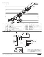
Preparing to Paint
Before painting, it is important to make sure that the fluid in the
system is compatible with the paint that is going to be used.
NOTE: Incompatible fluids and paint may cause the
valves to become stuck closed, which would
require disassembly and cleaning of the
sprayer’s fluid section.
IMPORTaNT: always keep the trigger lock on the spray gun
in the locked position while preparing the system.
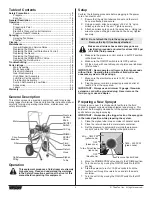
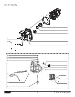
1. Place the siphon tube into a container of the appropriate
solvent. Examples of the appropriate solvent are water for
latex paint or mineral spirits for oil-based paints.
2. Place the return hose into a metal waste container.
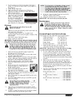
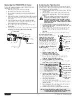
Max.
PSI
Clean
Min.
PSI
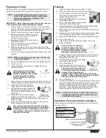
3. Set the pressure to minimum by turning
the pressure control knob to the “Min”
setting in the yellow zone.
4. Move the PRIME/SPRAY valve down to
the PRIME position.
5. Turn the unit on by moving the ON/OFF
switch to the ON position.
6. Allow the sprayer to run for 15–30 seconds to flush the
old solvent out through the return hose and into the metal
waste container.
7. Turn the unit off by moving the ON/OFF switch to the OFF
position.
NOTE: Make sure that the spray gun does not have a tip
or tip guard installed.
8. Move the PRIME/SPRAY valve up to the SPRAY position.
9. Turn the unit on.
10. Unlock the gun by turning the gun trigger lock to the
unlocked position.
Ground the gun by holding it
against the edge of the metal
container while flushing. Failure
to do so may lead to a static
electric discharge, which may
cause a fire.
11. Trigger the gun into the metal waste container until the old
solvent is gone and fresh solvent is coming out of the gun.
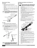
Trigger lock
in locked position.
12. Lock the gun by turning the gun
trigger lock to the locked position.
13. Set down the gun and increase the
pressure by turning the pressure
control knob slowly clockwise into the
green zone.
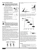
14. Check the entire system for leaks.
If leaks occur, follow the “Pressure
Relief Procedure” in this manual before tightening any
fittings or hoses.
15. Follow the “Pressure Relief Procedure” in this manual
before changing from solvent to paint.
Be sure to follow the pressure relief procedure
when shutting down the sprayer for any purpose,
including servicing or adjusting any part of the
spray system, changing or cleaning spray tips, or
preparing for cleanup.
Painting
1. Place the siphon tube into a container of paint.
2. Place the return hose into a metal waste container.
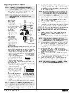
Max.
PSI
Clean
Min.
PSI
3. Set the pressure to minimum by turning
the pressure control knob to the “Min”
setting in the yellow zone.
4. Move the PRIME/SPRAY valve down to
the PRIME position.
5. Turn on the sprayer by moving the ON/
OFF switch to the ON position.
6. Allow the sprayer to run until paint is coming through the
return hose into the metal waste container.
7. Turn off the sprayer by moving the ON/OFF switch to the
OFF position.
8. Remove the return hose from the waste container and place
it in its operating position above the container of paint.
9. Move the PRIME/SPRAY valve up to the SPRAY position.
10. Turn on the sprayer.
11. Unlock the gun by turning the gun trigger lock to the
unlocked position.
Ground the gun by holding it
against the edge of the metal
container while flushing. Failure to
do so may lead to a static electric
discharge, which may cause a fire.
12. Trigger the gun into the metal waste container until all air
and solvent is flushed from the spray hose and paint is
flowing freely from the gun.
Trigger lock
in locked position.
13. Lock the gun by turning the gun trigger
lock to the locked position.
14. Turn off the sprayer.
15. Attach tip guard and tip to the gun as
instructed by the tip guard or tip manuals.
POSSIBLE INJEcTION haZaRD.
Do not spray without the tip guard
in place. Never trigger the gun
unless the tip is in either the spray or the unclog
position. always engage the gun trigger lock before
removing, replacing or cleaning tip.
16. Turn on the sprayer.
17. Increase the pressure by turning the pressure control knob
slowly clockwise toward the green zone and test the spray
pattern on a piece of cardboard. Adjust the pressure
control knob until the spray from the gun is completely
atomized. Try to keep the pressure control knob at the
lowest setting that maintains good atomization.
NOTE: Turning the pressure up higher then needed to
atomize the paint will cause premature tip wear
and additional overspray.
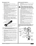
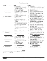
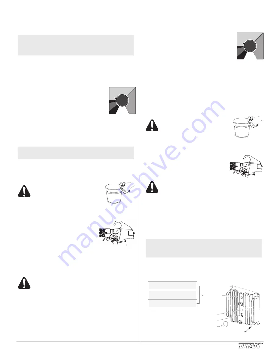
Electronic Pressure control Indicators
The following is a description of the indicators on the electronic
pressure control.
Pressure
Indicator
Motor Running Indicator
Programmer Port
Programmer Port
Dust Cover
Circuit
Breaker
Blinking Yellow =
0 PSI – priming pressure
Solid Yellow =
priming pressure – 1800 PSI
Solid Green =
1800 PSI – 3300 PSI


