6
© Titan Tool Inc. All rights reserved.
START-UP PROCEDURES
Step 1: Prepare the Paint
A. Prepare the material to be sprayed
according to paint manufacturers
recommendations.
B. Strain the paint before each use. 770-
119 Cone Strainer provided.
C. Thin the material to be sprayed with the
recommended solvent. Most materials
need to be thinned to obtain spraying
consistency. To achieve the proper
viscosity for spraying, either a viscosity
cup can be used or trial and error.
D. If a viscosity cup is not available, thin
the materials to a point where you will
achieve a one second interval between
drops after a paint stick has been
inserted and removed from paint.
Step 2: Gun and Turbine Set-Up
A. With the turbine switch in the off
position, plug into a grounded outlet at
least 20 feet from spray activity.
B. Attach air atomizing hose to turbine.
C. Attach quart cup to gun and attach tube
from gun to cup, attach air hose to
bottom of the gun. Make sure that
everything is secure before spraying.
Step 3: Spray Gun Adjustments
The “Pro-Finish” gun comes equipped with
a .051 fluid nozzle and needle and our #0
medium air cap. Always test your spray
pattern on a test surface before you
begin to work.
A. Fan size adjustment is controlled by
turning the air cap retainer ring.
Clockwise will increase fan width,
counterclockwise will decrease fan
width.
B. Top knob controls air volume. Clockwise
will decrease air flow.
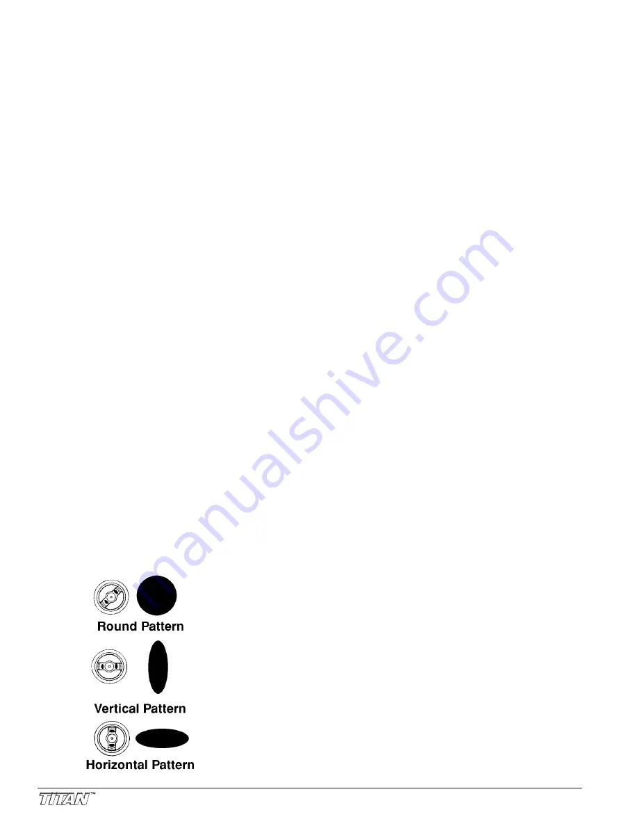
C. A round, horizontal or vertical fan
pattern can be achieved by rotating air
cap as shown by the diagrams below.
D. A round pattern will require less material
flow than a wide pattern. Turning the
lower knob clockwise will decrease fluid
flow; counter-clockwise will increase
fluid flow.
Step 4: Fluid Nozzle / Needle / Air Cap
Selection
If after all of the appropriate adjustments
are made poor results are obtained, it may
be necessary to change to a different fluid
nozzle / needle or air cap. Refer to our
selection chart to match the appropriate
components to the material being sprayed.
Note: The smaller the air cap the greater
atomization.
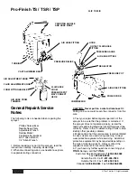
A. To change fluid nozzle and tip remove
air cap 101 and indexing retainer 103.
B. Squeeze trigger and with a wrench
remove fluid tip 105.
(Use Fluid Tip Tool ( 773-134), supplied,
not pictured)
C. Remove rear Adjustment Knob (128).
Remove Spring (127) and Needle (126)
D. Reassemble in reverse order A thru C.
Note: Never use lubricants containing
silicones. Silicone will adversely
affect spray finishes and is difficult to
get rid of once on equipment.
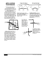
The following techniques are
recommended to assure
professional painting results. Hold
the gun perpendicular to the surface
and always at an equal distance of
approximately 6”-8”.
Move the gun either across or up
and down the surface at a steady
rate. Moving the gun at a consistent
speed provides even coverage. The
correct spraying speed allows for a
full wet coat of material without runs
or sags. Do not angle the gun as this
will cause uneven paint build-up,
runs or sags. Begin movement of
the gun before the trigger is pulled.
Holding the gun closer to the
surface deposits more paint on the
surface and produces a narrower
spray pattern. Holding the gun
farther from the surface produces a
thinner coat and wider spray pattern.
If runs, sags or excessive paint
occur, change to a spray tip with a
smaller orifice. Conversely, if there is
an insufficient amount of paint on
the surface or you desire to spray
faster, a larger orifice tip should be
selected.
USER'S MAINTENANCE
INSTRUCTIONS
During storage the power cord
must be coiled around cord holder to
avoid damage.
CLEANING PROCEDURES
The Titan Pro-Finish system has
been constructed with the finest
materials to assure trouble free
operation and durability.
However, like any paint tool,
proper cleaning is essential for
optimum performance to be
maintained. Always clean
thoroughly after each use.
Step 1. Pour remaining material in
the quart cup back into the original
container. For single component
materials ONLY. For catalyzed
material, consult coating mfg.
recommendation.
Step 2. Pour a small amount of
solvent in the cup. Swirl the solvent
around in the cup and empty.
Step 3. Thoroughly clean the interior
of the cup and wipe dry.
Step 4. Pour a small amount of
solvent into cup and spray through
the gun to clean fluid nozzle and
needle.
Step 5. After extended use it might
be necessary to remove the fluid
nozzle, needle and air cap and clean
by hand, with a soft brush. (Part No.
770-118 provided). Do not use a
wire brush or hard tools that could
damage the components. Also clean
the inside of the gun with solvent
and a soft brush. Reassemble gun
and test with mineral spirits.
Step 6. Clean the exterior of the gun
using solvent. NEVER soak the gun
in solvent. Some solvents can
damage internal seals.
Step 7. Check turbine filter, clean or
replace. (Never use solvent to
clean turbine filter, blow clean
with compressed air or replace.)
Please dispose of cleaning
solvent and unused coatings in
an environmentally safe fashion.
Consult with material
manufacturer on proper
procedure.


