© Titan Tool. All rights reserved.
3
English
Table of contents
Safety ......................................................................................... 2
Introduction ............................................................................... 3
Setup .......................................................................................... 3
Converting the Gun to Pressure Feed
................................. 3
Mounting the Turbine
.......................................................... 4
Connecting the Power Cart
................................................. 4
Hose Configurations
............................................................ 4
Preparing to Spray
.............................................................. 5
cleanup ..................................................................................... 5
Troubleshooting ....................................................................... 6
Parts List ............................................................................ 20-21
Warranty .................................................................................. 24
Introduction
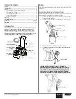
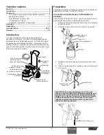
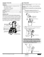
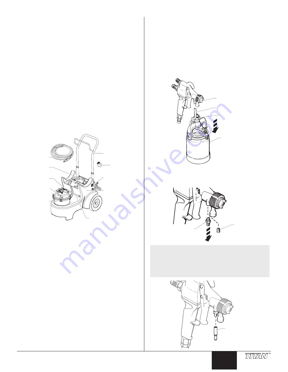
The HVLP power cart is designed for use with CAPspray spray
systems. The power cart adds tremendous versatility to an
already complete system. Components of the HVLP power
cart include a power switch, a cart, a pressure pot assembly, a
compressor assembly, a pressure pot inlet, a pressure pot hose,
a pressure pot outlet, a fluid hose, and a turbine bracket.
Pressure Pot
Air Inlet
Latch Bracket
3/8” X 30 ft
Fluid hose
Pressure Pot
Fluid Outlet
Pressure Pot
Assembly
Pressure Pot Air Hose
Power Switch
Compressor
Assembly
(inside housing)
Cart
Turbine
Bracket
Setup
Use the following procedures to set up your spray gun and HVLP
power cart.
converting the Gun to Pressure Feed
Before using the HVLP power cart, it is necessary to convert your
spray gun from a cup gun to a pressure fed gun.
1. Loosen the retaining nut using a wrench and remove the
one quart cup assembly.
2. Pull the air tube off of the air tube fitting on the spray gun.
Air Tube
Retaining Nut
Cup Assembly
Air Tube Fitting
3. Remove the air tube fitting using a 1/4” wrench.
4. Thread the set screw into the air tube fitting location and
tighten into place.
Set Screw
Air Tube Fitting
Optional (in place of steps 3 and 4): If desired, a
temporary cap (also included) can be used to close off
the air tube fitting rather than performing steps 3 and 4
above. This is a convenient method of capping the air
tube fitting if the operator will be frequently switching
back and forth between a 1-quart cup and a pressure pot.
Air Tube Cap


