


© Titan Tool Inc. All rights reserved.
3
Maintenance
Follow all safety precautions as described in the Safety
Precautions section of this manual before proceeding.
NOTE: Refer to the Parts list section in this manual for part
identification.
Replacing/Servicing the Seal Assembly
If your spray gun leaks or spits at the tip when you release the trigger,
the needle or seat is worn, damaged, or dirty and must be replaced or
cleaned.
Never attempt to perform maintenance on the spray gun
without first performing the “Pressure Relief Procedure.”
1. Disconnect the fluid hose from the gun.
2. Remove the tip and tip guard.
3. With the trigger depressed, remove the diffuser from the front of
the gun.
4. Remove the lock nut, rear housing, and retractor pins from the
rear of the gun head.
5. Remove the seal assembly from the front of the gun head by
pushing or gently tapping at the back of the seal assembly.
6. Soak the removed parts in the appropriate solvent and wipe
clean.
7. Inspect the parts for wear or damage and use new parts during
reassembly of the gun, when necessary.
NOTE: Lubricate all packings and moving parts before
reassembly with a lithium-based grease.
8. Install the seal assembly into the front of the gun head.
9. Install the retractor pins into the rear of the gun head. Slide the
rear housing onto the retractor pins and secure in position with
the lock nut.
10. WIth the trigger depressed, install the diffuser into the front of the
gun head and tighten securely with a wrench.
11. Perform the “Adjusting the Seal Assembly” procedure described
below.
Adjusting the Seal Assembly
Proper adjustment of the seal assembly is essential to
ensure positive shut-off when the trigger is released.
1. Tighten the lock nut until the rear housing is flush against the gun
head.
2. Unscrew the lock nut 3/4 of a turn.
NOTE: To check the adjustment of the seal assembly:
1. Move the gun trigger lock to the locked position.
2. Pull the trigger.
With the trigger lock engaged, there should be 1/32” of
movement between the lock nut and the rear housing
while pulling the trigger.
Replacing/Removing the Filter
1. Pull the bottom of the trigger guard forward so that it comes loose
from the handle assembly.
2. Loosen and remove the handle assembly from the gun head.
3. Pull the old filter out of the gun head.
4. Slide the new filter, tapered end first, into the gun head.
5. Make sure the handle seal is in position and thread the handle
assembly into the gun head until secure.
6. Snap the trigger guard back onto the handle assembly.
Gun Filter Chart
Part
Number
Application
Filter
Type
Color of
Filter
Body
0089960
Synthetic resin,
enamels, clean
varnishes, stains
azures
Extrafine
red
0089959
Base coat enamels,
primer enamels,
fillers, marking paints,
textured enamels
Fine
yellow
0089958
Emulsions,
latex paints,
acrylic paints
Medium
white
0089957
Filler paints,
large area surfaces
Coarse
green
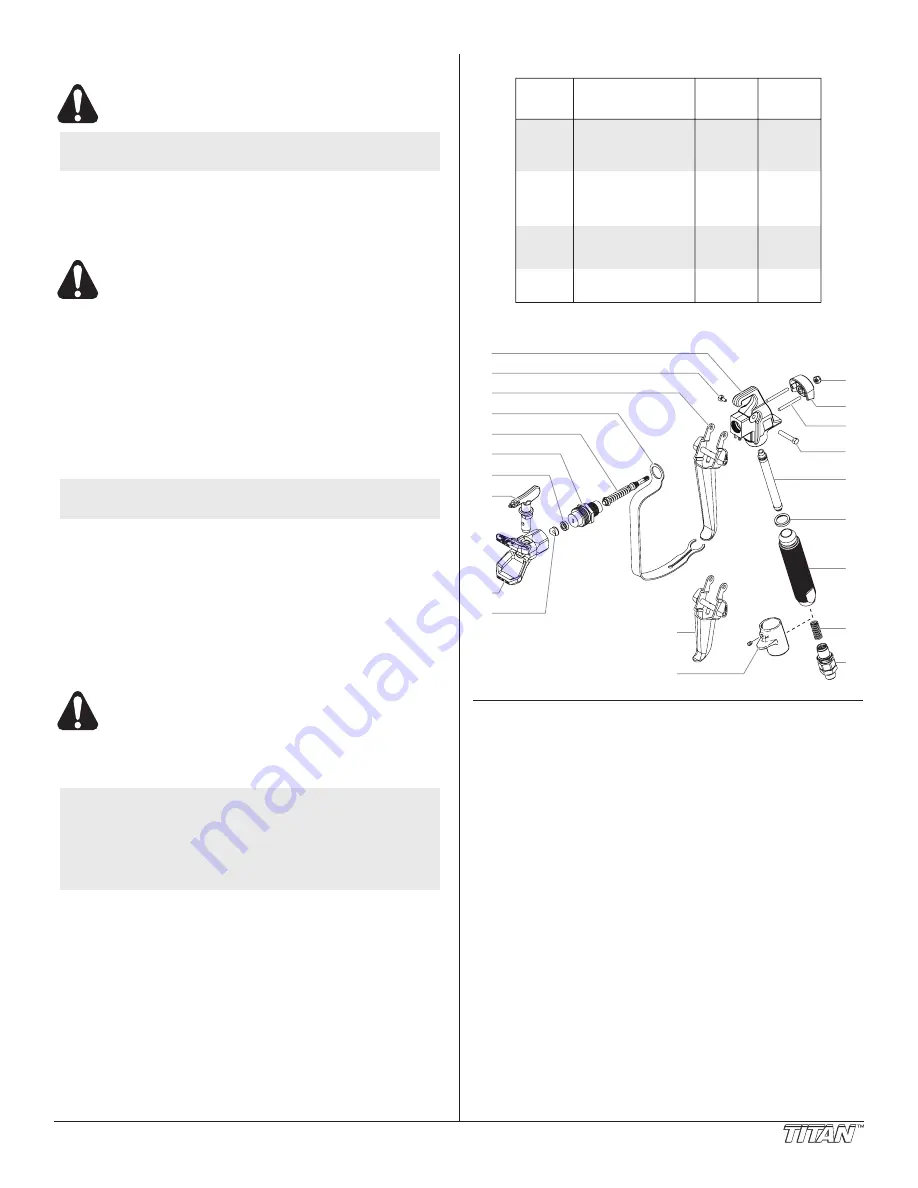
Parts list
1
2
3
4
5
6
7
8
9
20
21
10
12
13
14
15
16
17
18
19
11
Item Part #
description
Quantity
1
0296228
Gun head
..........................................................1
2
0296284
Trigger screw, short
..........................................1
3
0296285
Trigger assembly, 4-finger gun
.........................1
4
0296230
Trigger guard
....................................................1
5
0296270
Seal assembly
...................................................1
6
0296404
Diffuser
..............................................................1
7
0297045
Seal
...................................................................1
8
661-517
Tip assembly,
(includes items 7 and 10)
..................................1
9
661-012
Tip guard
..........................................................1
10
0297007
Tip seal
.............................................................1
11
9910201
Lock nut
............................................................1
12
0296222
Rear housing
.....................................................1
13
0296286
Retractor pin
.....................................................2
14
0296287
Trigger screw, long
...........................................1
15
0089958
Filter, medium
...................................................1
16
0296289
Handle seal
.......................................................1
17
0296342
Handle
...............................................................1
18
0296343
Spring
................................................................1
19
0347706
Swivel
................................................................1
20
0296291
Trigger assembly, 2-finger gun
.........................1
21
0279185
Collar assembly, 2-finger gun
...........................1
0296345
Handle assembly (includes items 17–19)
0296294
Gun repair kit (includes items 5, 6, and 11)


