background image

12


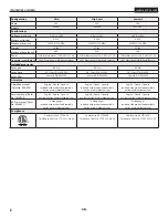
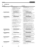
TROUBLESHOOTING

IMPACT 540

TROUBLESHOOTING

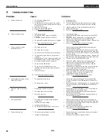
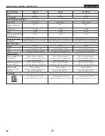
Problem


A.  The unit will not run.


B.  The unit will not prime.


C.  The unit will not build or 

maintain pressure.

  D.  Fluid leakage at the upper end 

of the fluid section.


E.  Excessive surge at the spray 

gun.


F.  Poor spray pattern.


  G.  The unit lacks power.

Cause


1.  The unit is not plugged in.


2.  Tripped breaker.


3.  The pressure is set too low (pressure control 

knob set at minimum setting does not supply 

power to unit).


4.  Faulty or loose wiring.


5.  Excessive motor temperature.


6.  ON/OFF switch is defective.


1.  Inlet valve is stuck.


2.  The PRIME/SPRAY valve is in the SPRAY 

position.


3.  Air leak in the siphon tube/suction set.


4.  The pump filter and/or inlet screen is clogged.


5.  The siphon tube/suction set is clogged.


1.  The spray tip is worn.


2.  The spray tip is too large.


3.  The pressure control knob is not set properly.


4.  The pump filter, gun filter, or inlet screen is 

clogged.


5.  Material flows from the return hose when the 

PRIME/SPRAY valve is in the SPRAY position.


6.  Air leak in the siphon tube/suction set.


7.  There is external fluid leak.


8.  There is an internal fluid section leak 

(packings are worn and/or dirty, valve balls 

are worn).


9.  Worn valve seats

  10.  Motor powers but fails to rotate


1.  The upper packing is worn.


2.  The piston rod is worn.


1.  Wrong type of airless spray hose.


2.  The spray tip worn or too large.


3.  Excessive pressure.


1.  The spray tip is too large for the material 

being used.


2.  Incorrect pressure setting.


3.  Insufficient fluid delivery.


4.  The material being sprayed is too viscous.


1.  The pressure adjustment is too low.


2.  Improper voltage supply.

Solution


1.  Plug the unit in.


2.  Reset the breaker.


3.  Turn the pressure control knob clockwise to supply 

power to the unit and increase the pressure setting.


4.  Inspect or take to a Titan authorized service center.


5.  Allow motor to cool.


6.  Replace the ON/OFF switch.


1.  Insert pusher stem.


2.  Rotate the PRIME/SPRAY valve clockwise to the PRIME 

position.


3.  Check the siphon tube/suction set connection and 

tighten or re-tape the connection with PTFE tape.


4.  Remove the pump filter element and clean.  Remove the 

inlet screen and clean.


5.  Remove the siphon tube/suction set and clean.


1.  Replace the spray tip following the instructions that 

came with the spray gun.


2.  Replace the spray tip with a tip that has a smaller orifice 

following the instructions that came with the spray gun.


3.  Turn the pressure control knob clockwise to increase the 

pressure setting.


4.  Remove the pump filter element and clean.  Remove the 

gun filter and clean.  Remove the inlet screen and clean.


5.  Clean or replace the PRIME/SPRAY valve.


6.  Check the siphon tube/suction set connection and 

tighten or re-tape the connection with PTFE tape.


7.  Check for external leaks at all connections.  Tighten 

connections, if necessary.


8.  Clean the valves and service the fluid section following 

the “Servicing the Fluid Section” procedure in the 

Maintenance section of this manual.


9.  Reverse or replace the valve seats following the 

“Servicing the Fluid Section” procedure in the 

Maintenance section of this manual.

  10.  Take unit to a Titan authorized service center.


1.  Repack the pump following the “Servicing the Fluid 

Section” procedure in the Maintenance section of this 

manual.


2.  Replace the piston rod following the “Servicing the Fluid 

Section” procedure in the Maintenance section of this 

manual.


1.  Replace hose with a minimum of 50’ of 1/4” grounded 

textile braid airless paint spray hose.


2.  Replace the spray tip following the instructions that 

came with the spray gun.


3.  Rotate the pressure control knob counterclockwise to 

decrease spray pressure.


1.  Replace the spray tip with a new or smaller spray tip 

following the instructions that came with the spray gun.


2.  Rotate the pressure control knob to adjust the pressure 

for a proper spray pattern.


3.  Clean all screens and filters.


4.  Add solvent to the material according to the 

manufacturer’s recommendations.


1.  Rotate the pressure control knob clockwise to increase 

the pressure setting.


2.  Reconnect the input voltage for 120V AC.

Summary of Contents for IMPACT 540 805-001

Page 1: ...HIGH PRESSURE SPRAYING UNIT GROUPE DE PROJECTION HAUTE PRESSION AIRLESS EQUIPO DE ALTA PRESI N PARA PULVERIZAR SERVICE MANUAL EN SERIVCE MANUAL 2 F MANUEL D ENTRETIEN 14 ES MANUAL DE MANTENIMIENTO 26...

Page 2: ...tion manual Form No 805 906 English French Spanish included with product and available online at www titantool com English French Spanish included with product and available online at www titantool co...

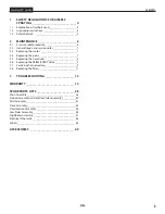
Page 3: ...lve_________________9 2 7 Servicing the fuid section________________________9 2 8 Replacing the filters____________________________11 3 TROUBLESHOOTING_____________________ 12 WARRANTY________________...

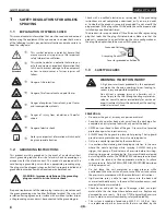
Page 4: ...g plug that looks like the plug illustrated below Make sure that the product is connected to an outlet having the same configuration as the plug No adapter should be used with this product Grounded Ou...

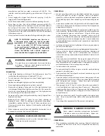
Page 5: ...pen flame pilot lights or sources of ignition such as hot objects cigarettes motors electrical equipment and electrical appliances Avoid creating sparks from connecting and disconnecting power cords U...

Page 6: ...evention and operation The United States Government Safety Standards have been adopted under the Occupational Safety and Health Act OSHA These standards particularly part 1910 of the General Standards...

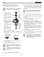
Page 7: ...r access to the control panel board 6 At the the control panel board disconnect the two wires coming from the motor refer to the electrical schematic in the Parts List section of this manual 7 Loosen...

Page 8: ...t the piston is in its lowest position 3 Perform the Pressure Relief Procedure and unplug the sprayer Before proceeding follow the Pressure Relief Procedure outlined previously in this manual Addition...

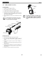
Page 9: ...er back for easy access to the fluid section Pump block Bushing Foot valve ball Foot valve seat PTFE O ring Foot valve O ring Foot valve seal Inlet cage Pusher stem housing SERVICING THE VALVES The de...

Page 10: ...the piston guide into the retainer nut Thread the retainer nut into the pump block until it is hand tight 12 Slide the piston guide tool included in the repacking kit over the top of the piston rod a...

Page 11: ...e filter housing should be hand tightened but make sure the filter housing is seated fully into the pump block Pump block Filter spring Filter housing Seal Filter support spring Filter Adapter GUN FIL...

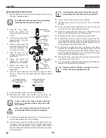
Page 12: ...se to the PRIME position 3 Check the siphon tube suction set connection and tighten or re tape the connection with PTFE tape 4 Remove the pump filter element and clean Remove the inlet screen and clea...

Page 13: ...o the factory if necessary are to be borne and prepaid by the End User Repaired or replaced equipment will be returned to the End User transportation prepaid THERE IS NO OTHER EXPRESS WARRANTY TITAN H...

Page 14: ...es d emploi Mode d emploi N de form 805 906 Anglais fran ais espagnol Inclus avec l appareil et disponible en ligne www titantool com Anglais fran ais espagnol Inclus avec l appareil et disponible en...

Page 15: ...RIME SPRAY_______21 2 7 Maintenance de la section des liquides____________21 2 8 Remplacement des filtres_______________________23 3 D PANNAGE____________________________ 24 GARANTIE__________________...

Page 16: ...ect une prise lectrique ayant la m me configuration que la fiche m le Ne pas utiliser d adaptateur avec ce produit Prise trifilaire Broche de mise la terre Plaque murale de la prise 1 3 DANGERS POUR L...

Page 17: ...masse Assurez vous que le tuyau air et les tuyaux de pulv risation sont dispos s de fa on viter les risques de glissade de tr buchement ou de chute RISQUE EXPLOSION ET INCENDIE Les vapeurs inflammable...

Page 18: ...uds avec le tuyau et ne le tordez pas trop Le tuyau vide peut pr senter des fuites suite l usure les n uds ou les mauvais traitements Une fuite risque d injecter du produit dans la peau N exposez pas...

Page 19: ...de montage panneau de contr le Tirez le panneau de contr le d acc s au panneau de bord 6 Sur le panneau de bord d brancher les deux fils venant du moteur se reporter au sch ma de raccordement lectriq...

Page 20: ...r l appareil Avant de proc der on doit suivre les directives de la section Proc dure de d compression du pr sent manuel On doit galement respecter tous les autres avertissements si on veut viter les b...

Page 21: ...arri re pour acc der plus facilement la section des liquides MAINTENANCE DES SOUPAPES Bloc pompe Manchon Clapet de la soupape de retenue Si ge de la soupape de retenue Joint torique de PTFE Logement d...

Page 22: ...Ins rer le guide piston dans l crou de retenue et visser fermement ce dernier la main dans le bloc pompe 12 Glisser l outil guide piston inclus dans la trousse de remplacement des tampons sur le dess...

Page 23: ...tre Logement du filtre Joint torique Ressort du support de filtre Filtre Adaptateur FILTRE DE PISTOLET 1 D tachez le dessus du pontet de la corps du pistolet 2 En se servant de la partie inf rieure du...

Page 24: ...dans le sens des aiguilles d une montre en position PRIME 2 V rifier le branchement du flexible du siphon d aspiration et serrer ou recoller le raccord avec du ruban en PTFE 3 D monter le filtre de la...

Page 25: ...is remplac es ou r par es les pi ces seront renvoy es ce dernier par transport pr pay AUCUNE AUTRE GARANTIE EXPLICITE N EST DONN E PAR LES PR SENTES TITAN SE D GAGE DE TOUTE AUTRE GARANTIE IMPLICITE I...

Page 26: ...es de instrucciones Instrucciones de uso N m de form 805 906 Ingl s franc s espa ol Incluido con la unidad y disponible en l nea en www titantool com Ingl s franc s espa ol Incluido con la unidad y di...

Page 27: ...ME SPRAY__________33 2 7 Servicio a la secci n de l quidos__________________33 2 8 Reemplazo de los filtros_________________________35 3 PROCEDIMIENTO EN CASO DE AVER AS____ 36 GARANT A_______________...

Page 28: ...ra utilizarse en un circuito de 120 voltios nominales y tiene un enchufe a tierra que tiene un aspecto similar al ilustrado m s abajo Aseg rese que el producto est conectado a un tomacorriente que ten...

Page 29: ...cen el peligro de deslizamientos tropiezos y ca das PELIGRO EXPLOSIONES E INCENDIOS Los vapores inflamables como los vapores de las pinturas y los solventes pueden encenderse o explotar en el rea de t...

Page 30: ...odelaLeydesaludyseguridadocupacional OSHA Deben consultarse tres normas particularmente la secci n 1910 de las Normas generales y la secci n 1926 de las Normas sobre construcci n Cada vez que vaya a u...

Page 31: ...gaste excesivo de los engranajes en la caja de la bomba Si es necesario reemplace los engranajes 10 Instale el motor nuevo en la caja de la bomba 11 Asegure el motor con sus cuatro tornillos de montaj...

Page 32: ...el riesgo de una lesi n por inyecci n lesiones por piezas en movimiento o choque el ctrico Siempre desenchufe el rociador antes de darle servicio 4 Incline la bomba hacia atr s para ingresar m s f ci...

Page 33: ...lvula de pie 5 Incline la bomba hacia atr s para ingresar m s f cilmente a la secci n de l quido SERVICIO A LAS V LVULAS Bloque de la bomba Buje Bola de la v lvula de pie Asiento de la v lvula de pie...

Page 34: ...sar fugas 11 Inserte la gu a del pist n en la tuerca de retenci n Atornille la tuerca de retenci n en el bloque de la bomba hasta que quede firme manualmente 12 Deslice la herramienta de la gu a del p...

Page 35: ...la bomba Bloque de la bomba Resorte del filtro Caja del filtro Sello Resorte del soporte del filtro Filtro Adaptador FILTRO DE LA PISTOLA 1 Desenganche la parte superior del guardamonte desde el estru...

Page 36: ...de las agujas del reloj hasta la posici n PRIME 3 Compruebe la conexi n del tubo de sif n juego de succi n y apriete o vuelva a asegurar la conexi n con cinta PTFE 4 Quite el elemento del filtro de bo...

Page 37: ...ecesario deben ser costeados y pagados por adelantado por el Usuario Final El equipo que se repare o reemplace se devolver al Usuario Final con los gastos de env o pagados por adelantado NOEXISTEOTRAG...

Page 38: ...E CUADRO DE PIEZAS DE RECAMBIO IMPACT 540 EN MAIN ASSEMBLY F ENSEMBLE PRINCIPAL ES CONJUNTO PRINCIPAL 38 38 25 24 28 26 27 29 Cart model Mod le de chariot Modelo de carro 30 1 3 4 5 15 14 12 11 13 20...

Page 39: ...rol panel screw Vis de panneau de contr le Tornillo de panel de control 4 19 704 358 Plug Capuchon Tapa 2 20 805 207A Fluid section assembly skid and low rider Ensemble de section des liquides support...

Page 40: ...e d aspiration comprend les articles 1 7 Ensamblaje del juego de succi n incluye articulos 1 7 1 2 9850638 Tie wrap Cord d amarrage Amarra 2 3 0558659A Return tube Tube de retour Tubo de retorno 1 4 0...

Page 41: ...Pata derecha 1 4 0294635 Plug Fiche Tap n 1 5 805 342 Foot Pied Pie 1 6 700 642 Cord wrap screw Vis de embobineur Tornillo de soporte para envolver el cable el ctrico 2 7 0294635 Plug Fiche Tap n 1 8...

Page 42: ...MOTEUR ES CONJUNTO DEL MECANISMO IMPULSOR 42 1 2 3 4 5 6 8 9 10 12 13 11 7 i All electrical work should be performed by an authorized service center i Tous les travaux d lectricit doivent tre effectu...

Page 43: ...e de but e Arandela de empuje 1 5 704 173A Crankshaft gear assembly Ensemble vilebrequin engrenages Ensamblaje cig e al engranaje 1 6 805 264A Motor assembly Ensemble de moteur Ensamblaje del motor 1...

Page 44: ...seaut doivent tre vers le haut Bord biseaut Instale la empaquetadura inferior con borde biselado hacia arriba Borde biselado 1 8 9 10 11 12 13 14 15 16 17 18 19 20 21 22 23 24 2 3 4 5 7 6 NOTE When us...

Page 45: ...ncluye art culo 22 carro 1 24 805 350 Pusher assembly clip Agrafe de ensamble de poussoir Agrafe de ensamblaje de v stago impulsor 1 25 730 067 Filter Filtre Filtro 1 26 702 251 Adapter Adaptateur Ada...

Page 46: ...590 508 Roll pin Goupille rouleau Pasador de rollo 2 5 590 506 Handle washer Rondelle de manche Arandela del mango 2 6 590 504 Handle sleeve Manche Manga de asa 2 7 9841504 Spring button Bouton d enc...

Page 47: ...278 Handle Poign e Mango 1 2 9841504 Spring button Bouton d enclenchement Bot n a presion 2 3 590 504 Handle sleeve Manche Manga de asa 2 4 805 281 Cart Chariot Carro 1 5 0278373 Wheel Roue Rueda 2 6...

Page 48: ...aci n soporte P N 805 404A Power Cord cart and lowboy cart Cordon d alimentation chariot et basse chariot Cable de alimentaci n carro y bajo carro Capacitor Capaciteur Capacidor Surge suppressor Prote...

Page 49: ...e embout 45 cm Extensi n de punta 45 cm 651 073 24 Tip Extension Rallonge de embout 60 cm Extensi n de punta 60 cm 310 390 3 Extension Pole Tige rallonge de 3 po Barra de extensi n de 90 cm 310 391 6...

Page 50: ...50 UNITED STATES SALES SERVICE INTERNATIONAL WEB www titantool com PHONE 1 800 526 5362 1770 Fernbrook Lane Minneapolis MN 55447 EMAIL international titantool com IMPACT 540...

Reviews: