background image

OPERATION INSTRUCTIONS

Warning! Before using your sander be 

sure  to  read  the  instruction  manual 

carefully.


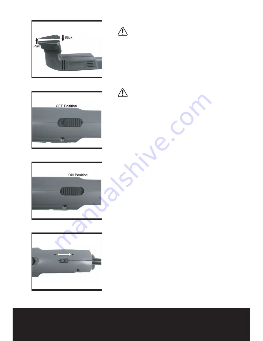
1. FITTING THE SANDING PAPER 

(See Fig2)

(a)Make sure the plug is disconnected from the 

mains supply.

(b)Align the dust extraction holes in the sanding 

pad with the holes in the base and press firmly 

together (see fig2).

(c)Spare sanding sheets can be purchased from 

any good DIY store.

Warning! Always switch off and unplug 

from  the  mains  before  making  any 

adjustment.

2. SWITCHING ON AND OFF 

(See Fig3a & 3b)

To  operate  the  detail  sander,put  the  plug  into 

mains  supply(make  sure  On/Off  switch  is  in  Off 

position see fig3a), grip sander firmly with both 

hands and switch on (see fig3b). At all times, let 

the sander do the work - do not force it or apply 

excessive  pressure,  otherwise  damage  may 

occur to the abrasive paper causing it to tear or 

wrinkle.  Preferably,  use  a  light  circular  motion. 

The sander can also be used on slightly curved 

surfaces,  owing  to  the  rubber-made  base  plate. 

The  shaped  base  plate  can  be  used  to  access 

awkward corners / areas.


3. VARIABLE SPEED CONTROL 

(See Fig4)

According  to  the  material  to  be  sanded  and 

sanding  paper  specification,  you  can  adjust 

sanding  speed  by  turning  the  speed  selector 

wheel.  The  greater  speed  is  indicated  by  the 

higher figure. The little speed is indicated by the 

lower figure.               


4. USING THE SANDER

 (See Fig5)

Note:

  If  you  see  some  sparks  flashing  in  the 

ventilation slots do not panic, this is normal and 

will not damage the tool.

Be sure to hold the sander firmly whilst it is on 

and apply it gently to the work; it may kick on first 

contact. Hold the sander so that it is flat on the 

work and move slowly, preferably in parallel line 

movements. When you first turn it on, make sure 

that your finger remains on the switch so you can 

STOP the sander in case there is a problem.

Fig 3a

Fig 3b

Fig 2

Fig 4

Summary of Contents for SF280E

Page 1: ...280W DETAIL SANDER SF280E SAFETY AND OPERATING MANUAL...

Page 2: ...f routine maintenance Failure of consumable items such as batteries Accidental damage Cosmetic damage Failure to follow manufacturer s guidelines Loss of use of the goods Repairs attempted by anyone u...

Page 3: ...the cord Never use the cord for carrying pulling or unplugging the power tool Keep cord away from heat oil sharp edges or moving parts Damaged or entangled cords increase the risk of electric shock e...

Page 4: ...reakage of parts and any other condition that may affect the power tools operation If damaged have the power tool repaired before use Many accidents are caused by poorly maintained power tools f Keep...

Page 5: ...lation The tool is double insulated This means that all the external metal parts are electrically insulated from the mains power supply This is done by placing insulation barriers between the electric...

Page 6: ...1 ON OFF SWITCH 2 VARIABLE SPEED SELECTOR WHEEL 3 CONNECTION TO DUST EXTRACTION 4 GRIP HANDLE 5 SANDER BASE 6 SANDING SHEET 6 5 4 1 2 3...

Page 7: ...Power input 280W No load speed 3000 10000min 1 Base size 90 x 90 x 90mm Double insulation Weight 1 41kg ACCESSORIES Sanding paper 2pcs 80 and 120 Grit NOISE AND VIBRATION DATA Sound pressure level 83...

Page 8: ...using it to tear or wrinkle Preferably use a light circular motion The sander can also be used on slightly curved surfaces owing to the rubber made base plate The shaped base plate can be used to acce...

Page 9: ...ise your nish 5 ATTACHING SANDER TO VACUUM See Fig6 Your sander is equipped with a dust extraction adapter which is designed for collect dust task Insert the dust adapter into the rear dust outlet of...

Page 10: ...paper will only abrade if in good condition replace the paper and try again The paper must be kept in a dry place If it is allowed to become damp the abrasive particles will lose their adhesion to th...

Page 11: ...new plug follows the instruction below IMPORTANT The wire in the mains lead are coloured in accordance with the following code Blue Neutral Brown Live The wire that is coloured blue must be connected...

Page 12: ...quirements of the following directives 89 336 EEC 93 68 EEC EMC Directive 73 23 EEC 93 68 EEC Low Voltage Directive 98 37 EC Machinery Directive Standards and technical speci cations referred to EN550...

Page 13: ......

Reviews: