background image


40 

 © Titan Tool Inc.  All rights reserved. 

United States Sales & Service

1770 Fernbrook Lane

Minneapolis, MN 55447

www.titantool.com

200 Trowers Road, Unit 7B

Woodbridge, Ontario L4L 5Z8

Phone:

Fax:

1-800-526-5362
1-800-528-4826

Phone:

Fax:

1-800-565-8665
1-800-856-8496

Canadian Branch

1770 Fernbrook Lane

Minneapolis, MN  55447

Phone:

Fax:

1-201-337-1240
1-201-405-7449

International

Titan Warranty for the commander™ airless Sprayers

Titan Tool, Inc., (“Titan”) warrants that at the time of delivery to the original purchaser for use (“End User”), the equipment covered 

by this warranty is free from defects in material and workmanship. With the exception of any special, limited, or extended warranty 

published by Titan, Titan’s obligation under this warranty is limited to replacing or repairing without charge those parts which, to Titan’s 

reasonable satisfaction, are shown to be defective within twelve (12) months after sale to the End User.  This warranty applies only 

when the unit is installed and operated in accordance with the recommendations and instructions of Titan.
This warranty does not apply in the case of damage or wear caused by abrasion, corrosion or misuse, negligence, accident, faulty 

installation, substitution of non-Titan component parts, or tampering with the unit in a manner to impair normal operation.
Defective parts are to be returned to an authorized Titan sales/service outlet.  All transportation charges, including return to the 

factory, if necessary, are to be borne and prepaid by the End User.  Repaired or replaced equipment will be returned to the End User 

transportation prepaid.

THERE IS NO OTHER EXPRESS WARRANTY.  TITAN HEREBY DISCLAIMS ANY AND ALL IMPLIED WARRANTIES INCLUDING, 

BUT NOT LIMITED TO, THOSE OF MERCHANTABILITY AND FITNESS FOR A PARTICULAR PURPOSE, TO THE EXTENT 

PERMITTED BY LAW.  THE DURATION OF ANY IMPLIED WARRANTIES WHICH CANNOT BE DISCLAIMED IS LIMITED TO 

THE TIME PERIOD SPECIFIED IN THE EXPRESS WARRANTY.  IN NO CASE SHALL TITAN LIABILITY EXCEED THE AMOUNT 

OF THE PURCHASE PRICE.  LIABILITY FOR CONSEQUENTIAL, INCIDENTAL OR SPECIAL DAMAGES UNDER ANY AND ALL 

WARRANTIES IS EXCLUDED TO THE EXTENT PERMITTED BY LAW.
TITAN MAKES NO WARRANTY AND DISCLAIMS ALL IMPLIED WARRANTIES OF MERCHANTABILITY AND FITNESS FOR 

A PARTICULAR PURPOSE WITH RESPECT TO ACCESSORIES, EQUIPMENT, MATERIALS OR COMPONENTS SOLD BUT 

NOT MANUFACTURED BY TITAN.  THOSE ITEMS SOLD, BUT NOT MANUFACTURED BY TITAN (SUCH AS GAS ENGINES, 

SWITCHES, HOSES, ETC.) ARE SUBJECT TO THE WARRANTY, IF ANY, OF THEIR MANUFACTURER.  TITAN WILL PROVIDE 

THE PURCHASER WITH REASONABLE ASSISTANCE IN MAKING ANY CLAIM FOR BREACH OF THESE WARRANTIES.

Material Safety Data Sheets (MSDS) are available on Titan’s website or by calling Customer Service.

Summary of Contents for SPEEFLO Admiral 830-331

Page 1: ...prayer Model Numbers 741 440 761 301 761 411 741 331 Printed in the U S A 0910 Titan Tool Inc All Rights Reserved Form No 0528924B NOTE This manual contains important warnings and instructions Please read and retain for reference Do not use this equipment before reading this manual ...

Page 2: ...ible DO NOT delay treatment to research toxicity Toxicity is a concern with some coatings injected directly into the blood stream Consultation with a plastic surgeon or reconstructive hand surgeon may be advisable HAZARD HAZARDOUS VAPORS Paints solvents insecticides and other materials can be harmful if inhaled or come in contact with the body Vapors can cause severe nausea fainting or poisoning P...

Page 3: ... not overreach or stand on an unstable support Keep effective footing and balance at all times Use lowest possible pressure to flush equipment Stay alert and watch what you are doing Do not operate the unit when fatigued or under the influence of drugs or alcohol For electric units Always unplug cord from outlet before working on equipment Do not use the hose as a strength member to pull or lift t...

Page 4: ... 4 NPT F Hose connection 1 2 NPT F Approximate air requirement per gallon of output 100 psi air pressure 17 SCFM 0 48m3 min Air inlet 1 2 NPT F 30 1 Gallons per minute GPM 4 0 Liters per minute LPM 15 1 Cycle rate per gallon 20 Cycle rate per liter 5 3 Maximum tip size 2000 psi 0 55 Pressure ratio 30 1 Maximum pressure 3000 psi 20 7 MPa 207 bar Fluid inlet 1 NPT F Fluid outlet 3 4 NPT F Hose conne...

Page 5: ...shed rods and cylinders give maximum abrasion and corrosion resistance with minimum friction Result long life Tungsten carbide valve seats with hardened stainless steel check balls prevent fluid cutting and resist plugging Long Life Packings are also standard Self adjusting pressure compensated spring loaded packings ensure proper seal and long life Standard packing sets of leather and UHMWPE ultr...

Page 6: ...detailed grounding instructions 3 Ventilation Areas must be well ventilated to prevent hazardous operation with volatile solvents or exhaust fumes 4 Connecting compressor to the sprayer Tighten the air hose wrench tight The air hose has factory installed Teflon ape on the male end of the hose See figure below 5 Connecting the paint hoses The siphon hose and the bleed line hose have factory install...

Page 7: ... are spraying a water based latex flush with warm soapy water followed by a clean water rinse If you are using any other coating flush with warm soapy water followed by a solvent Check with the material manufacturer for a compatible solvent 6 Place waste container below bleed line 7 Open pressure bleed valve 8 Open self relieving vented shutoff valve The handle should now be in line with the valve...

Page 8: ...ger lock in the Trigger Locked position Release the trigger lock and resume spraying Color Change Clean Out important Use only compatible solvents when cleaning out oil based enamels lacquers coal tar and epoxies Check with the fluid manufacturer for a recommended solvent 1 Reduce pressure by following the Pressure Relief Procedure The pressure bleed valve should be turned counter clockwise three ...

Page 9: ...rosene and oil mixture be introduced as a preservative Packings may tend to dry out from lack of use The is particularly true of the upper packing set for which upper packing lubricant Lubrisolv Titan Part No 310 200 is recommended in normal usage A sample of Lubrisolv accompanies each new unit Do not substitute water or paint solvent for Lubrisolv Ordinary oil may contaminate the paint material a...

Page 10: ... stroke faster than the other Packings are worn or valve balls are not seating Restriction in the siphon system Check siphon hose assembly to be sure no air is entering then recheck all threaded fittings for leakage See Troubleshooting Fluid Section for additional service information F Spitting Air in system Dirty gun Inspect for siphon hose leak Disassemble and clean gun G Gun does not spray any ...

Page 11: ...e Switch to bigger siphon set If tightening upper packing nut does not correct change upper packings B Pump delivers on down stroke only or goes up fast and down slowly Upper ball is not seating due to trash or wear Lower packing set is worn Check upper seat and ball with water If ball fails to seal seat replace Replace packing set is worn C Pump moves up and down fast not delivering material Mate...

Page 12: ...12 Titan Tool Inc All rights reserved Commander Series Portable Models 1 3 3 7 7 2 5 6 4 2 8 8 1 ...

Page 13: ...or Assembly set Fluid pump assembly 1 1c 742 140 742 557 140 100 140 556 Motor pump assembly Air motor Assembly set Fluid pump assembly 1 1 2 928 513 Air assembly 3 4 1 1 1 1 1 3 590 301 Cart assembly heavy duty 1 1 1 1 1 4 840 208 Outlet assembly 3 4 1 4a 840 205 Outlet assembly 1 2 1 5 920 554 Filter assembly outlet 5000 psi 1 1 5a 920 605 Filter assembly outlet manifold 6000 psi 1 6 840 209 Ble...

Page 14: ...14 Titan Tool Inc All rights reserved Commander Series Wall Mount and Drum Mount Models 1 4 9 3 1 2 2 6 6 8 5 ...

Page 15: ...183 101 185 551 Motor pump assembly drum mount Air motor Assembly set Fluid pump assembly 1 1e 742 559 742 557 142 102 155 559 Motor pump assembly Air motor Assembly set Fluid pump assembly 1 1f 742 140 742 557 140 100 140 556 Motor pump assembly Air motor Assembly set Fluid pump assembly 1 2 928 513 Air assembly 3 4 1 1 1 1 1 1 1 3 219 600 Drum cover assembly 55 Gal 1 1 4 590 300 Bracket assembly...

Page 16: ...40 925 Valve 1 1 20 738 224 O ring 2 2 21 740 985 Keeper lower valve 1 1 Item No Part No Description 742 557 742 555 QTY QTY 22 742 011 Bushing 1 1 23 742 223 O ring 1 1 24 890 114 O ring 1 1 25 742 016 Clip retainer 1 1 26 738 985 Nut piston 1 1 27 742 005 Washer piston 1 1 28 743 011 Valve rod assembly 1 1 29 850 917 PIston 1 1 30 850 016 O ring 1 1 31 743 227 Collar valve trip 1 1 32 738 937 Ro...

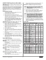
Page 17: ...properly seated in the O ring grooves 2 Place valve trip collar 31 into piston rod 32 followed by valve rod assembly 28 3 Screw piston rod 32 into piston 29 Replace piston nut and washer 26 27 4 Install new piston O ring 30 into piston 29 5 Place new gasket 33 into position in motor base 37 6 Place piston assembly 29 32 into motor base 37 Do not damage O ring 7 Place new O rings 20 on air valve 19...

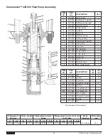
Page 18: ...9 138 001 Retainer spring 1 10 142 003 Spring packing 1 11 138 154 Lower leather packing set 1 12 138 225 Ball 1 13 143 945 Piston seat assembly 1 14 138 031 Gasket 2 15 138 032 Ball stop 1 16 138 340 Ball 1 17 140 991 Valve foot 1 18 818 010 Elbow 1 142 100 Assembly Set Item No Part No Description QTY 19 870 401 Nut 2 20 870 004 Washer 6 21 140 016 Stanchion 2 22 441 955 Rod connecting 1 23 866 6...

Page 19: ...all ball stop 15 between the two new cylinder gaskets 14 3 Connect foot valve 17 to cylinder 6 4 Place new packing set 11 over piston seat 13 important Peak of V packings must point down towards foot valve 17 5 Insert new packing set 3 into pump block 1 important Peak of V packings must point up towards the air motor 6 Insert displacement rod 8 through pump block 1 holding packings 3 in place with...

Page 20: ...73 O ring 2 12 155 932 Cylinder 1 13 174 113 Stop ball 1 14 174 102 Cage ball 1 15 178 700 Ball S S 1 16 155 991 Valve foot 1 142 100 Assembly Set Item No Part No Description QTY 18 140 016 Stanchion 2 19 441 956 Rod connecting 1 20 868 101 Nut 1 21 870 004 Washer 6 22 870 401 Nut 2 1A 19 4 5 6 7 8 3 9 10 11 12 11 13 14 15 16 18 1 20 2 22 21 3 Displacement Rod Area Stroke Length Displacement Volum...

Page 21: ...mble with new ball 9 spring 8 washer 7 and displacement rod 6 in that order Tighten and use Loctite on clean threads 2 Insert new upper packing set 3 into pump block 2 important Peak of V packings must point upwards on reassembly Install upper packing spring 4 and spring retainer 5 3 Insert displacement rod assembly 6 through pump block 2 holding upper packing set 3 in place with fingers 4 Lubrica...

Page 22: ...Cage ball 1 15 178 700 Ball S S 1 16 155 981 Valve foot 1 17 742 223 O ring Buna 1 18 174 001 O ring Teflon 1 19 920 103 Ball 1 142 101 Assembly Set Item No Part No Description QTY 20 868 101 Nut 2 21 870 004 Washer 2 22 870 005 Washer spacer 4 23 140 016 Stanchion 2 24 441 956 Rod connecting 1 25 138 007 Nut coupling Not included in this assembly Displacement Rod Area Stroke Length Displacement V...

Page 23: ...cking set 4 from pump block 3 13 Clean and inspect all parts Inspect rod or pump tube s hard chrome for grooves dents or worn areas Replace if hard chrome is damaged Inspect valve seats and replace if cracked or worn Reassembly Procedure 1 Insert upper packing set 4 into pump block 7 important Peak of V packings must point upwards on reassembly 2 Insert upper spring 5 small end of spring must go t...

Page 24: ...1 18a 241 109 Pin 1 142 100 Assembly Set Item No Part No Description QTY 19 870 401 Nut 2 20 870 004 Washer 6 21 140 016 Stanchion 2 22 442 956 Rod connecting 1 868 101 Nut not shown 1 183 101 Assembly Set for 55 gallon drum cover Item No Part No Description QTY 19a 870 401 Nut 2 20 870 004 Washer 6 21a 314 024 Stanchion 2 22 442 956 Rod connecting 1 22a 180 979 Extension connecting rod 1 23 868 1...

Page 25: ... downward on reassembly 5 Replace spring 10 spring retainer 9 and new ball 12 on piston seat 13 6 Thread piston seat 13 back onto displacement rod 2 important Use Loctite on clean threads 7 Insert displacement rod 2 assembly through upper packing set 4 in pump block 3 8 Place new O ring 7 on end of cylinder 8 and thread back into pump block 3 important Lubricate all O rings before assembly 9 Inser...

Page 26: ...S 1 17 245 021 Retainer cage 1 18 245 009 Rod displacement 1 Item No Part No Description 142 104 142 103 19 870 401 Nut 2 2 20 870 004 Washer 6 6 21 140 016 Stanchion 2 21a 314 024 Stanchion 55 Gal 2 22 245 109 Roll pin 1 23 442 959 Connecting rod 1 23a 441 959 Connecting rod 1 24 138 007 Nut coupling 25 180 980 Extension conrod 1 26 441 968 Stirrup 1 27 870 021 Nut 2 Not included in this assembly...

Page 27: ...ds on reassembly 2 Insert upper spring 3 small end of spring must go toward the packing set 3 Insert spring retainer 4 and new O ring 5 into pump block 1 important Lubricate all O rings before assembly 4 Place new lower packing set 10 over piston seat 11 important Peak of V must point downward on reassembly 5 Replace spring 9 spring retainer 8 and ball 7 on piston seat 13 6 Thread piston seat back...

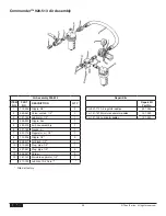
Page 28: ...ipple hex 1 5 542 015 Air hose assembly 1 6 227 100 Gauge air 1 7 921 712 Regulator air 1 2 1 8 112 204 Nipple 1 2 2 9 928 917 Air block 1 2 1 10 210 023 Plug pipe 1 2 1 11 227 027 Plug pipe 1 2 3 12 858 647 Screw 2 13 141 157 Moisture separator 1 2 1 311 100 Lubricant Air Care Filled at factory Repair Kits Repair Kit Part No For 921 712 Air regulator order 921 054 For 141 157 Moisture separator o...

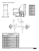
Page 29: ...t No Description QTY 1 590 352 Handle 1 2 935 014 End cap 2 3 590 350 Frame 2 4 862 410 Nut 3 8 16 10 5 862 001 Washer 3 8 14 6 862 472 Screw 3 8 16 x 2 1 4 10 7 590 351 Bracket 1 8 590 353 Axle 1 9 670 105 Wheel 16 inch 2 10 870 003 Washer 2 11 570 010 Cotter key 2 Cart Dimensions A 17 3 8 B 26 3 4 C 24 1 2 D 8 E 24 1 4 F 9 1 4 G 34 1 4 H 2 I 43 5 8 J CL of pump ...

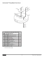
Page 30: ...iption QTY 1 860 535 Screw HH 5 16 18 x 7 8 4 2 862 452 Screw HH 3 8 16 x 1 5 1 3 219 506 Knob plastic 1 4 219 505 Plate inspection 1 5 219 555 Cover 55 Gal Drum 1 6 860 003 Washer flat 5 16 4 7 860 502 Nut Ela Stp 5 16 18 4 8 738 213 Spring 1 9 862 001 Washer flat 3 8 1 10 862 411 Nut Flex Lock 3 8 16 1 11 219 504 Plate adapter Not included in this assembly ...

Page 31: ... 4 4 860 502 Nut 4 4 5 191 444 Nipple extension 1 For use with outlet filters and surge chambers Wall Brackets Item No Part No Description 590 300 590 303 1 590 351 Bracket 1 1 2 3 4 5 6 7 219 100 860 535 219 504 860 502 860 003 191 444 Mounting kit Screw 4 Adapter plate 1 Nut 4 Washer 4 Nipple 1 1 2 3 4 5 6 219 200 860 535 219 504 860 502 860 003 Mounting kit Screw 4 Adapter plate 1 Nut 4 Washer ...

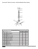
Page 32: ...000 psi 1 1 1a 920 930 Cap filter 6000 psi 1 2 920 103 Ball S S 1 1 1 3 920 004 Screen filter 50 mesh 1 1 3a 920 005 Screen filter 100 mesh 1 4 920 006 Gasket Teflon thick 1 1 1 5 920 070 Gasket Teflon thin 1 1 1 6 920 927 Body filter 5000 psi 1 1 6a 920 931 Body filter 6000 psi 1 7 812 003 Nipple hex 1 1 1 8 227 027 Plug pipe 1 1 9 227 033 Plug pipe 1 1 1 10 200 555 Adapter swivel 1 1 10a 200 554...

Page 33: ...d filter cap 1 with appropriate solvent Use care in handling parts as dirt debris scratches or nicks may prevent O rings or gaskets from sealing The 920 Series Filter Elements filter from the inside out Be certain to clean the screen element thoroughly on the inside Soak in solvent to loosen hardened paint etc or replace Part No 920 050 Filter Service Kit Item No Part No Description QTY 2 920 103 ...

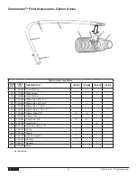
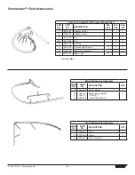
Page 34: ... 103 550 Siphon tube 3 4 x 17 1 2a 103 595 Siphon tube 3 4 x 36 1 2b 103 585 Siphon tube 1 x 36 1 2c 103 641 Siphon tube 1 1 4 x 17 1 3 103 682 Clamp hose 1 2 2 2 3a 103 679 Clamp hose 1 2 2 4 420 650 Hose fluid 3 4 3 6 4a 420 700 Hose fluid 1 6 4b 604 125 Hose assembly 1 1 4 1 5 103 130 Spring 1 1 5a 103 125 Spring 1 6 103 119 Clip hose guard 1 1 1 7 194 661 Adapter 1 1 7a 194 771 Adapter 1 8 205...

Page 35: ...04 Tee 1 1 3 929 063 Bushing 2 2 4 945 600 Pressure bleed valve 1 1 1 5 103 106 Bleed line assembly 1 1 1 6 813 555 Nipple hex 1 Not illustrated 840 209 Bleed Line Assembly Item No Part No Description QTY 1 944 620 Valve bleed 1 2 3 4 103 101 103 117 538 030 Bleed line assembly Tube 1 Hose assembly 1 1 103 106 Bleed Line Assembly Item No Part No Description QTY 1 103 317 Tube 1 2 201 555 Elbow 1 3...

Page 36: ...t rotates and wears evenly If there is leakage replace the ball important Open the adjustment knob 1 to full counterclockwise position before unthreading valve seat 9 from valve body 4 If the valve stem 3 is rotated inwardly with the ball removed the Teflon O ring 5 may require replacement If there has been leakage from the valve stem the Teflon O ring should be replaced important The valve stem s...

Page 37: ... Assemblies item no part no Description 975 102 975 104 975 111 975 302 975 304 975 311 2 gun 1 4 4 gun 1 4 1 gun add on 1 4 2 gun 3 8 4 gun 3 8 1 gun add on 3 8 1 970 100 Manifold 1 2 1 2 2 940 553 Valve ball 2 4 1 2a 941 555 Valve ball 2 4 1 3 814 002 Nipple hex 2 4 1 4 814 004 Nipple hex 1 2 3 6 1 5 227 006 Nipple hex 2 4 1 6 808 555 Nipple hex 2 4 1 7 227 033 Plug pipe 1 1 1 1 ...

Page 38: ...versible tip and 250 514 1 4 x 50 3300 psi airless hose assembly 711 002 Gun and hose kit for architectural coatings includes 520 100 gun with 641 517 SC 5 reversible tip and 250 114 1 4 x 50 5000 psi airless hose assembly 160 124 Nylon paint strainer 1 gallon pack of 24 160 524 Nylon paint strainer 5 gallon pack 24 101 208 Grounding clamp 101 212 Grounding wire 12 gauge x 25 310 203 Lubrisolv upp...

Page 39: ... Titan Tool Inc All rights reserved 39 Notes ...

Page 40: ...h the unit in a manner to impair normal operation Defective parts are to be returned to an authorized Titan sales service outlet All transportation charges including return to the factory if necessary are to be borne and prepaid by the End User Repaired or replaced equipment will be returned to the End User transportation prepaid THERE IS NO OTHER EXPRESS WARRANTY TITAN HEREBY DISCLAIMS ANY AND AL...

Reviews: