background image

 Installation of the UMAP 2110


1.4  Configuration Import/Export 

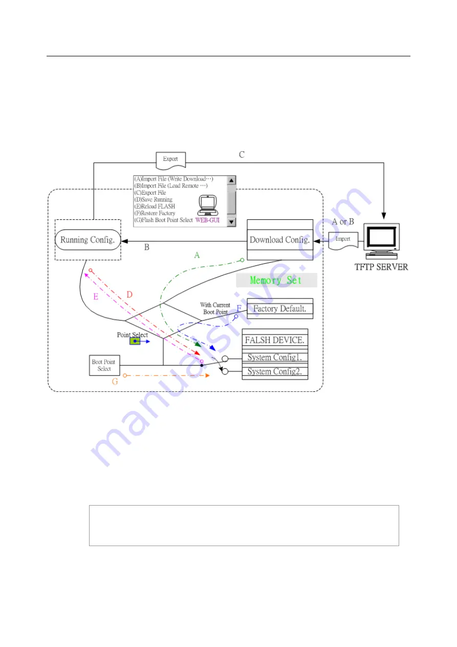
The UMAP 2110 provides the configuration preservation feature that the configuration database is 
stored in flash memory (two partitions available). In addition to the configuration preservation 
feature, the UMAP 2110 also provides the configuration export/import feature. 


Figure 1-14   DB Configuration Concept 

In CLI: 

Suppose that TFTP Server IP address is 172.16.100.181 and configuration file name is ‘testcfg’: 


(A) 

Import file from TFTP Server to the Download Config and then write Download Config to the 

Flash (partition 1 or partition 2). 

Ex: 

enable 

configure 

remotecfg login 

172.16.100.181

 get 

testcfg 

write


partition <number>


22 / 54 

Summary of Contents for UMAP 2110

Page 1: ...UMAP 2110 IP Digital Subscriber Line Access Multiplexer HW Installation and User Guide Part Number A0 31 0115 2 2 Issue 2 2 September 2008 ...

Page 2: ......

Page 3: ...r system meets regulatory requirements Danger 1 When removing cards from a chassis under power some of the components such as the DC converters may be extremely hot Handle by the card guides only Warning1 This unit contains no user serviceable parts Refer servicing to qualified personnel Warning 2 To prevent accidental electrical short circuits align the card correctly between the card guides befo...

Page 4: ...mplies with the Product Safety Requirements identified in EN 60950 IEC 60950 Electromagnetic The system complies with the FCC Part 15 Class A EN 55022 IEC 61000 Surge Protection The system complies with IEC 61000 4 5 RoHS and WEEE The system complies with the RoHS and WEEE II ...

Page 5: ... 1 2 5 Connecting the ADSLx and POTS interfaces 11 1 2 6 Connecting the GBE trunk interface 12 1 2 7 Ethernet Port MGMT 13 1 2 8 Console Port COM 14 1 2 9 Housekeeping and Alarm Contact Output Interface 15 1 3 Provisioning a Management IP port 17 1 4 Configuration Import Export 22 1 5 Firmware Update 32 2 Operating and Maintaining the UMAP 2110 37 2 1 Maintenance requirement 38 2 1 1 Tools and Equ...

Page 6: ...s 3 1 Introduction to Troubleshooting 46 3 2 Resolving Problems Indicated Through LEDs 46 3 3 Resolving Problems Indicated Through Alarms 47 3 4 Procedures for Troubleshooting the UMAP 2110 47 Abbreviations IV ...

Page 7: ...r panel 9 Figure 1 6 FAN Port RJ 45 pin assignment 10 Figure 1 7 Pin Assignment of LINE and POTS Interfaces 11 Figure 1 8 Connecting optical fiber to the trunk port 12 Figure 1 9 Ethernet Port RJ 45 pin assignment 13 Figure 1 10 Console Port RJ 45 pin assignment 14 Figure 1 11 Pin Assignment of Console Cable 14 Figure 1 12 Pin assignment of Housekeeping Inputs and Alarm Contact Output 15 Figure 1 ...

Page 8: ... 2 1 Required Installation Tools and Materials 38 Table 2 2 Procedures of Powering Up the DSLAM 40 Table 2 3 Procedures of Powering Down the DSLAM 40 Table 2 4 UMAP 2110 Controls and LED Indication 41 Table 3 1 Problems Indicated by LEDs 46 Table 3 2 List of Troubleshooting Procedures 47 VI ...

Page 9: ...w to manage the DSLAM through Command Line Interface CLI commands refer to the UMAP 2110 CLI Command Reference Guide For information about how to manage the DSLAM through Web GUI refer to the UMAP 2110 Web Configuration Tool Guide Documentation Conventions The following conventions are used in this manual to emphasize information that will be of interest to the reader Danger The described activity...

Page 10: ...2 54 ...

Page 11: ...3 54 1 Installation of the UMAP 2110 1 1 Pre Installation 1 2 Hardware Installation 1 3 Provisioning a Management IP Port 1 4 Configuration Import Export 1 5 Firmware Update ...

Page 12: ... injury do not apply power to the UMAP 2110 system at the central office or any remote site until you ve completed all of the installation procedures and connected it to the external facilities Be cautious when turning on off the UMAP 2110 system power 1 1 3 Electrostatic Discharge Protection The terminal cards contain static sensitive components When handling them be sure to wear a properly groun...

Page 13: ...ill be explained in detail in the following sections Step 1 Mount the system into the desired location of a rack Step 2 Turn the power switch in OFF position Connect to the DC power supply and then check the voltage Make sure the power switch is in OFF position before wiring the power cable and grounding Step 3 Connect FAN cable Step 4 Connect the cable between system and MDF After executing the p...

Page 14: ...stalled at the specified location When mounting the chassis practice good safety habits Use two or more people to secure the chassis Relay rack mounting normally requires at least two people Step Action 1 Locate the chassis and obtain the appropriate chassis mounting hardware 2 Determine and obtain the tools required for the chassis mounting hardware 3 From the front of the relay rack position the...

Page 15: ...1 Installation of the UMAP 2110 For 23 Rack For 19 Rack Figure 1 3 Mounting Bracket Position for Standard Mount 7 54 ...

Page 16: ...to a well fused power supply After completing chassis installation please apply power to the fused power distribution panel feeding the chassis When using a DC voltmeter please check for proper voltage 60V 36V DC and make sure that the polarity is correct Warning Ensure that all power sources to the chassis power distribution panel are turned off during the connection Note It is recommended that t...

Page 17: ...e measured resistance from the grounding screw on the rear panel of the DSLAM refer to Figure 1 5 to CO GND is less than 5 Ohm then it can be assumed that the system is well grounded If the measured resistance is larger than 5 Ohm it is recommended to connect the grounding screw to CO GND using 14 or 12 AWG wire gauge conductor In Remote Cabinet The UMAP 2110 should be grounded by connecting a 14 ...

Page 18: ... panel of UMAP 2110 One is on the FAN card the other is beside the housekeeping HK port To make the fans work you must use an RJ45 to RJ45 connector cable to connect the two FAN ports 1 2 3 4 5 6 7 8 3 4 5 6 7 8 GND FAN ERR1 FAN ERR2 FAN ERR3 FAN Status Figure 1 6 FAN Port RJ 45 pin assignment 10 54 ...

Page 19: ... illustrated below the numbers in the connector figures below represent PIN numbers For port 1 24 1 25 26 50 PIN Number 1 2 3 4 5 6 7 8 18 19 20 21 22 23 24 25 Port Number Tip 1 Tip 2 Tip 3 Tip 4 Tip 5 Tip 6 Tip 7 Tip 8 Tip 18 Tip 19 Tip 20 Tip 21 Tip 22 Tip 23 Tip 24 X PIN Number 26 27 28 29 30 31 32 33 43 44 45 46 47 48 49 50 Port Number Ring 1 Ring 2 Ring 3 Ring 4 Ring 5 Ring 6 Ring 7 Ring 8 Ri...

Page 20: ...lowing figure and table 1 2 T Rx T Rx 3 6 T Rx T Rx 4 5 T Rx T Rx 7 8 T Rx T Rx Mini GBIC SFP Trunk Port Prepare a proper SFP module and install it into the optical trunk port Then you can connect fiber optics cabling that uses LC connectors or SC connectors with the use of an optional SC to LC adapter to the fiber optics connector on the trunk port Fiber optics cable with LC duplex connector Conn...

Page 21: ...TX TX RX RX Bob Smith Termination Figure 1 9 Ethernet Port RJ 45 pin assignment To connect the Ethernet interface to PC the Ethernet crossover cable is required The detailed pin assignment is shown below Brown 1 Green White 8 Green 7 Orange White 6 Blue 5 Blue White 4 Orange 3 Brown White 2 8 Green White 1 Orange 2 Orange White 3 Brown 4 Blue White 5 Blue 6 Brown White 7 Green Name Pin Pin Name Tx...

Page 22: ...re 1 10 Console Port RJ 45 pin assignment To connect the host PC to the console port a RJ45 male connector to RS232 DB9 female connector cable is required The RJ45 connector of the cable is connected to the COM port of the DSLAM the DB9 connector of the cable is connected to the PC COM port The pin assignment of the console cable is shown below DB 9F RJ 45M Pin 1 2 Pin 2 RD 3 Pin 3 TD 4 5 Pin 5 DG...

Page 23: ...tect the open or close status of the loop between HK_IN and HK_COM user does not need to feed 3 3v power into the circuit As to the alarm output there is a relay between ALMOUT and ALMCOM to control the status of the loop to be open or close to the alarm equipment close between ALMOUT and ALMCOM for alarm open if no alarm The pin assignment of housekeeping and alarm contact output interface is ill...

Page 24: ...o nm e nt S e n so r U M A P 2 11 0 A la rm E qu ipm en t A L M O U T A L M C O M Figure 1 13 Operation diagram of Housekeeping Inputs and Alarm Contact Output Note The maximum current and voltage for ALMOUT ALMCOM is restricted to 0 5 A 30 VDC or 0 15 A 125 VAC resistive load 16 54 ...

Page 25: ...g command to check current IP setting of all the management ports enable Go to enable command mode show management all Display all system management port IP setting LOCAL login admin Password this is motd file to inform any information to user UMAP2110 System Description UMAP2110 48 port ADSL2 POTS Hardware Version C Firmware Version 0 77B03 Software Version 0 77B03 Compiled Tue Aug 26 21 21 29 CS...

Page 26: ... to configure command mode again runningcfg write partition number Save new settings to memory partition 1 or 2 After setting the in band out band IP of the UMAP 2110 remember to connect its Ethernet port MGMT to the Ethernet LAN Then in the previous PC terminal screen type the following commands to verify if the Ethernet connection between the management station and the UMAP 2110 is working exit ...

Page 27: ...s 172 16 10 72 ping statistics 4 packets transmitted 4 packets received 0 packet loss round trip min avg max 0 8 2 7 8 7 ms local Now you can access the UMAP 2110 via Telnet on port 23 for using CLI or Web GUI by entering its IP address in your browser s URL address field Besides CLI you can also change the in band out band management IP of the UMAP 2110 in the Web GUI a On the menu tree click on ...

Page 28: ...1 Installation of the UMAP 2110 20 54 ...

Page 29: ... menu tree click on Maintenance Database The Database Configuration page is displayed Click on the DB Config Select drop down list and select D Save Running Config to Flash Select write to Partition 1 or Partition 2 Then click on Write_Running button Wait for memory write success message 21 54 ...

Page 30: ... preservation feature the UMAP 2110 also provides the configuration export import feature Figure 1 14 DB Configuration Concept In CLI Suppose that TFTP Server IP address is 172 16 100 181 and configuration file name is testcfg A Import file from TFTP Server to the Download Config and then write Download Config to the Flash partition 1 or partition 2 Ex enable configure remotecfg login 172 16 100 1...

Page 31: ...e configure runningcfg login 172 16 100 181 put testcfg D Write Running config to the Flash partition 1 or partition 2 Ex enable configure runningcfg write partition number E Reload Flash data to the Running config Ex enable configure runningcfg load partition number F Set system configuration current boot point to factory default value Ex enable configure restore factory G Select Configuration Fl...

Page 32: ...page is displayed Select the database configuration action you want to perform A Import File Write Download Config To Flash Type in the TFTP Server IP address and the name of the file you want to download Then click on Get File button Write downloaded Config to Flash in progress Write to memory successfully 24 54 ...

Page 33: ...1 Installation of the UMAP 2110 Fail to Get File 25 54 ...

Page 34: ...P 2110 B Import File Load Remote Config to Running Config Type in the TFTP Server IP address and the name of the file you want to download Then click on Get File button Load to Running Config successfully Fail to Get File 26 54 ...

Page 35: ...MAP 2110 C Export File Put Running Config to Remote TFTP Server Type in the TFTP Server IP address and the name of the file you want to export Then click on Put File button TFTP put file successfully TFTP put file fail 27 54 ...

Page 36: ... 2110 D Save Running Config to Flash System Config Click on the drop down list and select partition and then click on Write_Running button to write running configuration to Flash Write running config to Flash successfully 28 54 ...

Page 37: ... Reload Flash to Running Config Click on the drop down list and select partition and then click on LOAD_FLASH button to load configuration from Flash to Running Config Load configuration from Flash to Running Config successfully 29 54 ...

Page 38: ...ount all other configuration will be restored to factory default Click on Factory_Default button to restore factory default configuration After loading default configuration to Flash successfully you must click on RESTART button to restart the system so that the configuration can take effect 30 54 ...

Page 39: ...Click on the Boot Config drop down list and select the partition Partition1 or Partition2 as the boot point Click on Apply button and then restart the system The system will restart and load the configuration in the partition you select into the running configuration 31 54 ...

Page 40: ... restart the system to run new firmware image Once you upgrade successfully you can t upgrade the second time unless you have restarted the system show firmware partition show partition information Current Version 0 71B09 Partition Version Date Status 1 0 71B09 2007 07 05 2 0 73B05 2007 07 10 Active Note the Active status of the firmware partition information means the active partition for next ti...

Page 41: ...lick on this button to start firmware update Firmware Update Remote FTP Server IP Type in the IP address of the FTP server Server User Name Type in the ftp user name Server Password Type in the ftp password File Name Type in the firmware filename Firmware Update Status This field shows current status of firmware update process Select firmware memory partition Partition 1 or 2 If you change to the ...

Page 42: ...en you update the firmware new firmware will be written to the partition that is not currently in use Partition Information FTP Get in progress The following message is displayed during getting file from FTP server Firmware Write in progress The Flash Write process may take a few minutes you must not turn off or reset the system during the process Firmware Write successfully When the Flash Write p...

Page 43: ...1 Installation of the UMAP 2110 35 54 ...

Page 44: ...1 Installation of the UMAP 2110 36 54 ...

Page 45: ...37 54 2 Operating and Maintaining the UMAP 2110 2 1 Maintenance Requirement 2 2 Powering the DSLAM Up or Down 2 3 Controls and LED Indication 2 4 Replacing Units ...

Page 46: ...ections to external facilities VF transmission and signaling test sets Testing faulty POTS Fuse and alarm panel For protection and simplifying troubleshooting 2 1 2 System Spares Always keep spares for the DSLAM at each central office for replacement purposes During the system trouble shooting procedures certain cards at the central office and or remote site will be required to be replaced 2 1 3 D...

Page 47: ...aintenance Always monitor the UMAP 2110 system performance at the central office remote sites using the SNMP It allows user to view the current system status alarm information and to take the necessary corrective action if a problem is reported Also keep each UMAP 2110 system site free of dust and other pollutant that could affect system performance In addition be sure to maintain the environment ...

Page 48: ...ing supplied to the DSLAM 5 Ensure that the fan card is installed 6 Ensure that the POTS lines subscriber lines and alarm equipment are connected 7 Slide the power switch on the faceplate to ON 8 Wait for a minute and then check the LEDs on the DSLAM If the LEDs show some problem refer to section 3 2 for information on how to resolve problems indicated through LEDs Table 2 3 Procedures of Powering...

Page 49: ...Power on phase SYS Red Self test fail Green Normal Operation Yellow At power on phase ALM Red Red Flash Major alarm set Major and Minor alarm set Yellow Minor alarm set Green Normal operation Green SFP interface activated GBE1 GBE2 Off RJ 45 interface activated DSL Status Green Green Flash Off Port is activated and linked Port is activated but not linked Disabled GBE1 Speed GBE2 Speed LED B on RJ ...

Page 50: ... providing system out band EMS Telnet control interface such as system monitor control or software upgrade COM RS 232 port connected to the terminal for monitoring and controlling the system HK RJ 50 port for housekeeping inputs and one alarm contact output FAN RJ 45 port for connection with the RJ 45 port on the front panel of fan card to provide power to the fan POTS RJ 21 connector 50 pin dual ...

Page 51: ...e power switch of the DSLAM to the OFF position 3 Remove the fan card to be replaced by doing the following steps a Turn the two screws on the faceplate of the fan card counterclockwise until they loosen the connection of the fan card to the DSLAM b Pull the fan card out about 2 inches and wait for a moment for the fan blades to stop completely c Pull the fan card completely out of the DSLAM and s...

Page 52: ...insert the air filter into the chassis slot before inserting the FAN card Because you will not be able to insert the air filter after the FAN card is secured in place 1 Put on the antistatic wrist strap and connect it to a grounding point 2 Slide the power switch of the DSLAM to the OFF position 3 Remove the fan card refer to Procedure 2 1 4 Pull the air filter out of the DSLAM 5 Slide the replace...

Page 53: ... Troubleshooting the UMAP 2110 3 1 Introduction to Troubleshooting 3 2 Resolving Problems Indicated Through LEDs 3 3 Resolving Problems Indicated Through Alarms 3 4 Procedures for Troubleshooting the UMAP 2110 ...

Page 54: ...by LEDs on the system front panel Table 3 1 Problems Indicated by LEDs LED Activity Problem Action Not lit even though DSLAM is powered up There is a power up problem with the system Troubleshoot the DSLAM for power up problems see section 3 4 SYS Red Self test failed There is a functional problem with the system Replace the UMAP 2110 Red Major alarm set See section 3 3 Red Flash Major and Minor a...

Page 55: ...rocedure If the first step does not solve the problem proceed to the next step keep going through the steps until the problem is solved Use the following table to find out the appropriate procedure for troubleshooting the listed problems Table 3 2 List of Troubleshooting Procedures Type of problem Procedure Number UMAP 2110 power up problems 3 1 Fan card power up problems 3 2 Fiber optics problems...

Page 56: ...ur provider Procedure 3 3 Troubleshoot Fiber Optics Problems Problem indication the GBE1 GBE2 LED on the system front panel is not lit maybe the signal power detected by the fiber optical receiver being below the minimum power threshold but the SFP interface has been activated alarm that indicates loss of signal subscribers connected to the DSLAM do not have DSL service POTS service is ok 1 Check ...

Page 57: ... check the SYS LED on the front panel if it is red replace the DSLAM 3 Check the GBE1 GBE2 LED if SFP interface is activated if it is not lit follow Procedure 3 3 to troubleshoot the DSLAM for fiber optics problems 4 If only some subscribers are affected identify the ports that have problems Check that the subscribers are connected to the line interfaces properly 5 Contact your provider Procedure ...

Page 58: ...in POTS service to the affected subscribers but there is still no ADSLx service to them follow Procedure 3 4 to troubleshoot ADSLx service problems If this step results in ADSL service to the affected subscribers but there is still no POTS service to them follow Procedure 3 5 to troubleshoot POTS service problems 2 Use a bridging connector to couple the POTS and subscriber lines If this results in...

Page 59: ...ne access multiplexer EMS element management system DSL digital subscriber line EMC electromagnetic compatibility EMI electromagnetic immunity ETSI European Telecommunications Standards Institute Mbps megabit per second MDF main distribution frame LED light emitting diode POTS plain old telephone service PSTN public switched telephone network PVC permanent virtual circuit SNMP simple network manag...

Page 60: ...52 54 ...

Page 61: ...53 54 ...

Page 62: ......

Reviews: