background image

EN

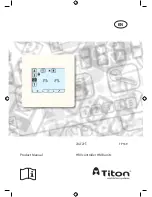
HRV controller HMB units

Product Manual

aura-t

 TP539

Summary of Contents for aura-t TP539

Page 1: ...EN HRV controller HMB units Product Manual aura t TP539 ...

Page 2: ...s 3 All wiring must conform to current I E E Wiring Regula tions and all applicable standards and Building Regula tions 4 aura t must be connected using the communication ca ble provided 5 Control communication cables should not be placed within 50mm or on the same metal cable tray as any 230V lighting or power cables 6 Ensure all cable glands are fully tightened 7 The unit must be stored in a cle...

Page 3: ...ave been given supervision or instruction concern ing use of the appliance in a safe way and understand the hazards involved 10 Children should be supervised to ensure that they do not play with the appliance 11 To avoid damaging the touch screen do not operate it with sharp or hard objects do not apply excessive finger tip pressure 12 Do not use abrasive cleaners waxes solvents or alcohol based c...

Page 4: ...ite ready 6 Enhanced aura t integrated or aura t connected 6 User Interface MenuTabs 12 Run Mode 13 Installation Location 15 Fixing 15 Wiring 16 Fan Commission 17 Commissioning 17 Cloning 18 Saving Fan Speeds to the aura t 18 Controller Setup 19 Summer Bypass Setup 21 Passcode Enable Disable 21 Eco Mode and Switch Setup Menu 22 Maintenance Cleaning Exterior 23 Appendix aura t Configurable Defaults...

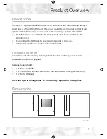
Page 5: ... units have a socket on the terminal box Supplied with a HMB unit to enable remote siting of the aura t Integrated into the unit not available with H200 Packaging Contents Inspect the unit when taking delivery Check the unit for damage and that all accessories have been supplied Package supplied with 1 x aura t controller 1 x 3m aura t communication cable not included with integrated versions 1 x ...

Page 6: ...with aura t connected or integrated Programmable Speeds The unit has 4 Speeds Speed 1 Setback Reduced ventilation Setback Speed is automatically set at the mid point between minimum possible Continuous Speed and the selected Continuous Speed Speed 2 Continuous Normal ventilation Speed 3 Boost Increased ventilation Continuous Boost speeds are commissioned using the basic controllers potentiometer S...

Page 7: ...of Speeds 1 3 4 can be assigned to any of the volt free switch inputs The unit speed can also be manually selected via the on screen 1 2 3 4 buttons icons which are also used to display any automatically selected speed Summer Bypass Summer Bypass is designed to operate during hot periods where fresh air can be vented straight into the property without being preheated by the extracted stale air Sum...

Page 8: ...ach of the switches can be configured to perform any one of the following functions o Wet Room Boost engages Speed 3 uses Wet Room Boost Overrun Timer o Kitchen Boost engages Speed 3 uses Kitchen Boost Overrun Timer o SUMMERboost Disable see right o Speed 1 Setback o Speed 4 o Off normally open switches off both fans o Off normally closed switches off both fans o Manual Summer Bypass engages bypas...

Page 9: ...PCB Automatic This is by means of a dedicated wall mounted room thermostat SUMMERboost will only operate when the temperature has exceeded the thermostat setting Should the room temperature fall below the thermostat setting then SUMMERboost will not operate Boost Overun Timer Variable between 0 and 60 minutes The Boost Speed can be triggered by any device which provides a volt free one way switch ...

Page 10: ...lter Change Alert Only available with auralite LED status indicator The aura t will display an alert after a specified time when the HRV filters require changing Eco Mode Not available After a one minute period of inactivity the LCD will switch off Status Icons LEDs with the auralite The aura t displays icons to indicates modes of operation in Real time Fan Speed Cloning Not available The current ...

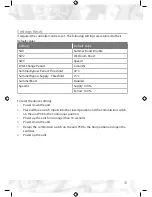
Page 11: ...shold 22 C Summer Bypass Supply Threshold 15 C SummerBoost Enabled Speed 4 Supply 100 Extract 100 To reset the above settings 1 Power down the unit 2 Place all three switch inputs into the closed position and the Commission switch on the unit PCB to the Continuous position 3 Power up the unit for no longer than 10 seconds 4 Power down the unit 5 Return the commission switch on the unit PCB to the ...

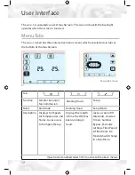
Page 12: ...nction Monitor Control Fan Commission Running Hours Setup Name Run Mode Running Hours Setup Mode Description Displays Fan Speed Air Temperatures and Status Gives access to Fan Speed Setup Displays the length of time the HRV has been running in hours Gives access to RH threshold Overrun Timers Summer Bypass Passcode settings Filter Period Filter Reset Eco Mode Switch Setup in a Sub Menu If passcode...

Page 13: ...disable Boost Inhibit Extract Supply Press the supply or extract buttons to cycle between fan speed and temperature With fan speed selected the actual percentage speed of both fans is displayed Selecting temperature displays the temperature of the air being supplied from the atmosphere and extracted from the property Status Icons If the fan speed is being controlled by an external switch or sensor...

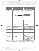
Page 14: ...irectly to the property without recovering heat from the Heat Cell This is often accompanied by SUMMERboost both fans switch to Speed 4 to increase the rate fresh air is supplied to the property and stale hot air is extracted Press Hold the 4 button to cancel SUMMERboost The Boost Overrun timer is active and is holding the HRV at Speed 3 this follows an external Boost switch being deactivated The ...

Page 15: ... control cable will reach Fixing 1 Un clip the front of the aura t case from the Back Plate 2 Thread the control cable through the hole in the Back Plate 3 Fix Back Plate 4 Connect the communication cable see Wiring section 5 Clip the front of aura t to the Back Plate Connection to HRV 60 Fixing Holes Wiring Access Hole ...

Page 16: ...e will be supplied fitted with a plug in connector for connection to the HRV 0V 12V A B Red White Yellow or Green Black 12V A B 0V Red White Yellow or Green Black Wire connection to HRV Connection to aura t typical plug connection to HRV ...

Page 17: ...rent fan speed is highlighted the HRV will run at the selected speed Extract Supply 2 Use the Supply to dwelling or Extract from dwelling buttons at the top of the screen to select which fan is to be adjusted 3 Use the arrow buttons to adjust the fan speed The fan will respond in real time to the adjustment being made 4 Repeat the above for all fan speeds requiring adjustment 5 When all of the fan...

Page 18: ...w buttons will be illuminated and the speeds could be adjusted as detailed in Commissioning or simply written to the HRV by tapping the Save button Saving Fan Speeds to the aura t Extract Supply To save the current fan speed to the aura t press and hold the Supply or Extract buttons The copy icon will be illuminated and when save is tapped the fan speeds will be saved to the aura t and written to ...

Page 19: ...ation is achieved by first Setting Selection and then Editing Setting Selection Arrow keys are used to select a setting the setting will flash Tapping the Enter key will allow the setting to edited Tap the Exit button to return to Run Mode Setting Editing Arrow keys are used to change setting value Tapping the Enter key whist editing will save and move to the next setting in the list ...

Page 20: ...Disable Enable 6 Filter Period 7 Filter Reset If a filter change is required the reset ring will be flashing Tap the Enter key to reset or the Exit key If a filter change is not due but the filter timer requires resetting press the Enter key twice Reset the filter timer if the Filter Period has been changed to initialise the new period Tap Exit key to return to Run Mode ...

Page 21: ... be adjusted Supply represents from atmosphere air temperature Extract represents from dwelling air temperature Tap button 4 to enable disable SUMMERboost Unfilled icon shown represents disabled Passcode Enable Disable Tap Enter key to edit state Use to enable disable Passcode indicates Passcode is disabled 3 3 3 3 indicates Passcode is enabled ...

Page 22: ...tab to enter the Eco Mode and Switch Setup Mode menu Select between and to enable or disable Eco Mode Switch Setup menu active All switch inputs to the HRV unit SW1 SW2 SW3 can be assigned any of the following functions Kitchen Boost Speed 3 Wet Room Boost Speed 3 Speed 1 Setback SUMMERboost disable Speed 4 Off Normally Open Off Normally Closed Manual Summer Bypass Boost Inhibit If Passcode is ena...

Page 23: ...ependently for Kitchen and Wet Room inputs Boost Overrun timers must be set greater than zero for any momentary switch to trigger boost When using latching switches to initiate Speed 3 Boost the Overrun timer will start when the latching switch is disengaged Proportional Humidity Set point 30 100 70 Proportional Humidity proportionally varies the fan speed between Continuous Speed 2 and Boost Spee...

Page 24: ...abled SUMMERboost operates in conjunction with Summer Bypass and switches the fans to Speed 4 It can also be disabled by a latching switch if fitted Filter Change Interval 1 month 24 months 6 months Display Mode ECO ON ECO Switch Inputs SW1 SUMMERboost Disable SW2 Wet Room Boost SW3 Speed 1 Setback Switch options are Kitchen Boost Wet Room Boost Speed 1 SUMMERboost disable Speed 4 OFF normally ope...

Page 25: ...x 44 0 1206 543126 Email ventsales titon co uk Web www titon com 2018 TITON DO 5666 Iss 01 In the event of any queries please contact the system installer Ensure this booklet is passed to the householder once installation commissioning of the ventilation system is complete This Product Manual must be kept in the Home Information Pack 25 ...

Reviews: