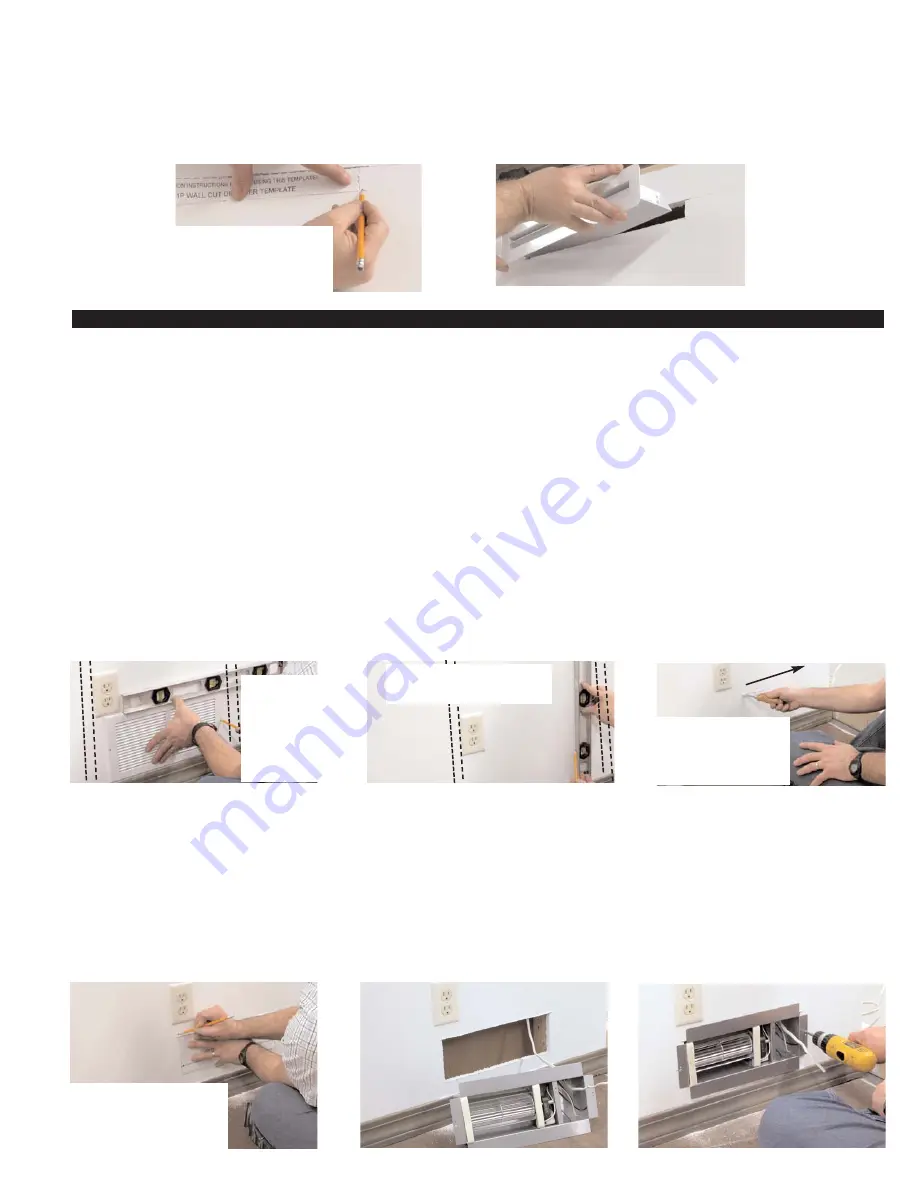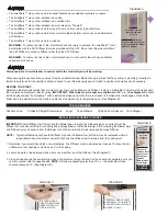
4. Cut out Diffuser template on dashed lines. Align the top of template with the wall cut and center it so that there is an equal space
between the right and left edges of the template and ends of the cut in the sheetrock. Mark all 4 corners of template, connect with
a straight edge and cut Diffuser opening in wall
(Diffuser opening should be 1 1/4” high x 13 5/8” wide)
, (See Diagram E).
5. Insert Diffuser with the air scoop on the back pointing towards the Blower. Adjust tangs on the sides if necessary to secure a tight fit
into the wall opening, (See Diagram F).
BLOWER INSTALLATION
IMPORTANT:
Install Diffuser first if mounting the Blower down low and the Diffuser high so sheetrock from the Diffuser cut out does not
fall into wall cavity and damage Blower. Install the Blower first if mounting the Blower high and Diffuser low so sheetrock from the
Blower cut out does not fall into wall cavity and damage Diffuser.
NOTE:
Typical installations will have the Diffuser high and the Blower low, but there may be instances where it is desirable to have
the Blower mounted high and the Diffuser low to take air from the ceiling level.
1. If installing in a stud wall section with an electrical outlet, place blower Intake Grille in desired position on stud wall verifying that the
bottom edge is above floor molding and that the top edge is below the bottom of any electrical outlet cover. Level top edge and mark
wall through the two mounting holes.
NOTE:
This is assuming the Blower is mounted down low and the Diffuser high., (See Diagram G).
If installing the Blower up high and the Diffuser low, the top of the blower Intake Grille must be mounted at least 2” below the ceiling.
2. Use a level to draw a vertical plumb line up 2 7/16” inches from each marked hole. Connect the top of the lines using a straight edge,
(See Diagram H).
3. Using a hand sheet rock saw carefully make a horizontal cut along the line going away from outlet. Cut the sheetrock completely until
you come in contact with the opposite stud.
NOTE:
If studs are spaced greater than 16” o.c., the horizontal cut line should not
exceed 14 1/2”, (See Diagram I).
5. Align the top of AS1 Blower template with the wall cut and center it so that there is an equal space between the right and left edges
of the template and ends of the cut in the sheetrock. Mark all 4 corners of template, connect with a straight edge and cut rectangular
opening in wall
(Model AS1 Blower opening should be 4 7/8” high x 13 7/8” wide)
, (See Diagram J).
6. Provide a switched 120 VAC power source with leads long enough to connect to the motor leads of the AireShare™ while it is posi-
tioned just outside Blower opening cut in sheetrock, (See Diagram K).
7. Carefully insert the Blower into the cutout. Level the top flange and mark the larger Blower flange mounting holes. Using the provided
wood screws, secure the blower to the wall studs. Use provided wall anchors if not installing into studs, (See Diagram L).
DIAGRAM H
DIAGRAM K
DIAGRAM L
DIAGRAM J
CENTER BLOWER TEMPLATE
ALONG SHEETROCK CUT AND
MARK 4 CORNERS. CUT OUT
AS1 BLOWER OPENING.
(4 7/8” HIGH x 13 7/8” WIDE)
MARK A VERTICAL PLUMB LINE
UP 2 7/16” FROM BOTH HOLES
MARKED THROUGH GRILLE
DIAGRAM E
DIAGRAM F
DIAGRAM I
CAREFULLY MAKE CUT
MOVING AWAY FROM
OUTLET TO OPPOSITE
STUD. CUT LINE SHOULD
NOT EXCEED 14”.
DIAGRAM G
CENTER DIFFUSER TEMPLATE
ALONG SHEETROCK CUT AND
MARK 4 CORNERS. CUT OUT
DIFFUSER OPENING.
(1 1/4” HIGH x 13 5/8” WIDE)
LEVEL INTAKE
GRILLE & MARK
HOLES. IF
INSTALLING UP
HIGH, TOP OF
GRILLE MUST
BE 2” BELOW
CEILING.


