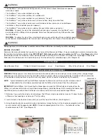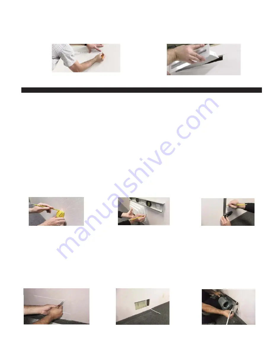
4. Cut out Diffuser template on dashed lines. Align the top of template with the wall cut and center it so that there is an equal space
between the right and left edges of the template and ends of the cut in the sheetrock. Mark all 4 corners of template, connect with
a straight edge and cut Diffuser opening in wall
(Diffuser opening should be 1 1/4” high x 13 5/8” wide)
, (See Diagram E).
5. Insert Diffuser with the air scoop on the back pointing towards the Blower. Adjust tangs on the sides if necessary to secure a tight fit
into the wall opening, (See Diagram F).
BLOWER INSTALLATION
WARNING:
Disrupt power at circuit breaker to outlets and switches within the stud wall you will be working. When sawing through
sheetrock you must stop if you detect the saw blade coming in contact with any wiring or plumbing. Investigate further to determine if it
is possible to safely continue to use this wall cavity space. Switch to another stud wall cavity if necessary.
NOTE:
Typical installations will have the Diffuser high and the Blower low, but there may be instances where it is desirable to have
the Blower mounted high and the Diffuser low to take air from the ceiling level.
IMPORTANT:
Install Diffuser first if mounting the Blower down low and the Diffuser high so sheetrock from the Diffuser cut out does not
fall into wall cavity and damage Blower. Install the Blower first if mounting the Blower high and Diffuser low so sheetrock from the
Blower cut out does not fall into wall cavity and damage Diffuser.
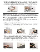
1. Using a stud finder mark the center of the stud on each side of the wall cavity that the AS2 Blower and Intake Grille will be installed,
(See Diagram G). These instructions assume standard 16” on center studs.
2. Position the AS2 Intake Grille at the desired height on the wall, centered between the two 16” on center studs. Level and lightly mark
the grille position through the two mounting holes.
IMPORTANT:
Make sure Intake Grille flanges do not interfere with baseboards &
outlets. If Intake Grille is mounted up high towards the ceiling, the top flange must be mounted 1” below the ceiling so Intake Grille
top opening clears double plate at top of stud walls, (See Diagram H).
3. Mark a level line 3 5/8” straight above and below each Intake Grille mounting hole and connect the tops and bottoms horizontally with
a Level, (See Diagram I).
4. Starting in the center of each line cut the dry wall using a hand saw until contact is made with one of the studs. Reverse the saw and
cut along the line in the opposite direction until contact is made with the opposite stud. Cut vertically along each stud to connect the
horizontal cuts and remove the dry wall
(AS2 Blower opening should be 7 1/4” high x 14 1/2” wide)
, (See Diagram J).
6. Provide a switched 120 VAC power source with leads long enough to connect to the motor leads of the AireShare™ while it is posi-
tioned just outside Blower opening cut in sheetrock, (See Diagram K).
7. Carefully insert the Blower into the cutout. Level the top flange and mark the larger Blower flange mounting holes. Using the provided
wood screws, secure the blower to the wall studs. Wire to AS2 using provided strain relief bushing, (See Diagram L).
DIAGRAM H
POSITION INTAKE GRILLE AT DESIRED HEIGHT,
LEVEL & MARK MOUNTING HOLES ON STUDS.
DIAGRAM E
DIAGRAM F
DIAGRAM I
MARK A LEVEL LINE 3 5/8” STRAIGHT ABOVE
AND BELOW GRILLE CENTER HOLES. LEVEL
TOPS & BOTTOMS OF LINES ACROSS.
DIAGRAM G
CENTER DIFFUSER TEMPLATE ALONG SHEETROCK
CUT AND MARK 4 CORNERS. CUT OUT DIFFUSER
OPENING. (1 1/4” HIGH x 13 5/8” WIDE)
INSERT DIFFUSER INTO WALL WITH AIR SCOOP
POINTING TOWARDS BLOWER.
USE STUD FINDER TO DETERMINE
CENTER OF STUDS IN CAVITY.
DIAGRAM K
PROVIDE SWITCHED 120 VAC POWER
SOURCE LEAD FOR BLOWER.
DIAGRAM L
SECURE BLOWER TO WALL AND
CONNECT 120 VAC POWER SOURCE
TO BLOWER MOTOR LEADS.
DIAGRAM J
CAREFULLY CUT BLOWER OPENING IN
SHEETROCK ALONG HORIZONTAL LINES
AND CONNECT ENDS VERTICALLY.


