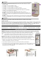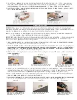
8. Secure J-box cover to Blower electrical box once wiring is
complete, (See Diagram M).
9. Attach Intake Grille to wall with provided screws, (See Diagram N).
WIRING
Disrupt power at circuit breaker to outlets and switches within the stud wall you will be working.
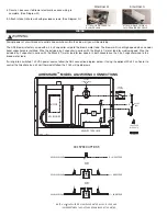
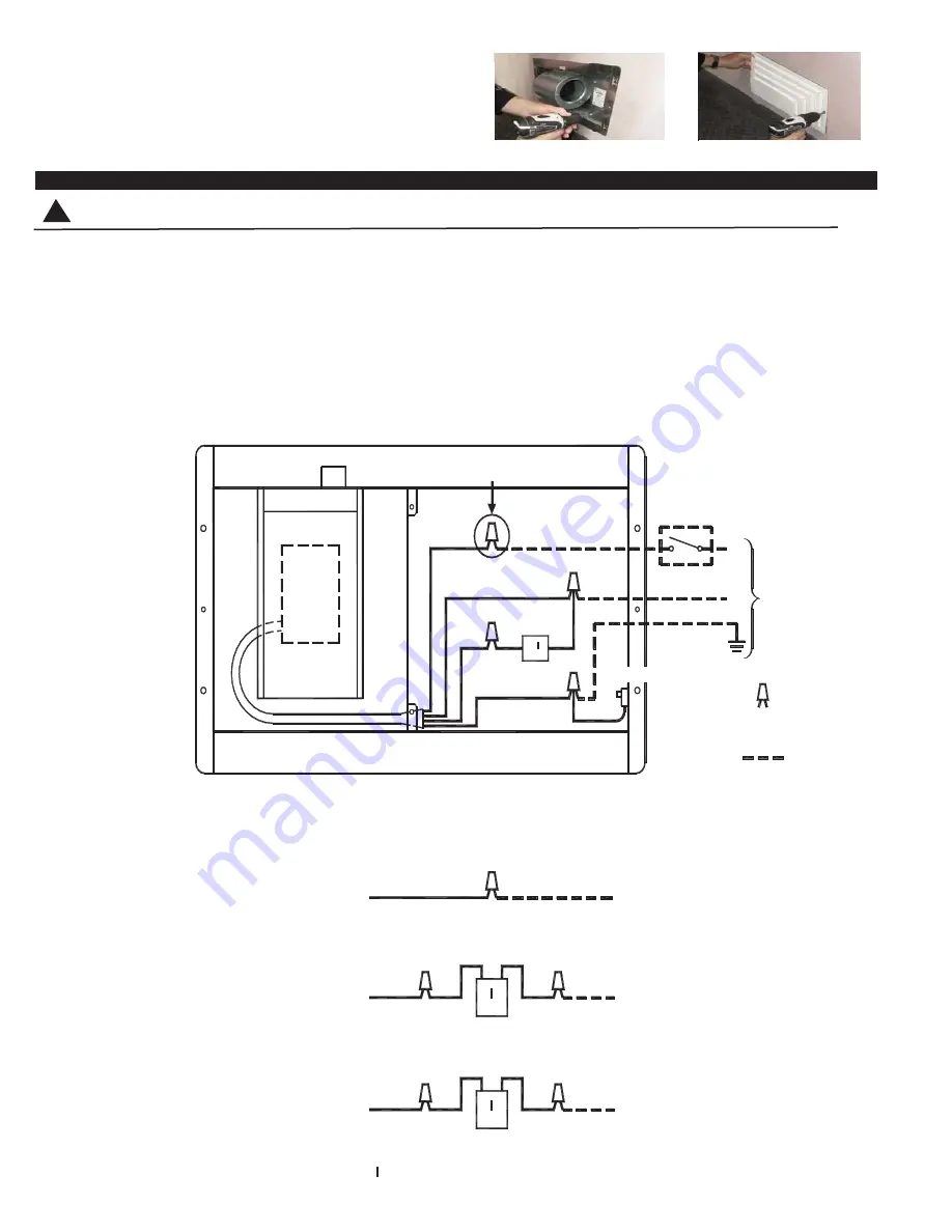
The AS2 blower is factory wired with a 2.5 µF capacitor wired to the brown motor lead. The blower will run at high speed when no addi-
tional capacitors are installed. Wire the included 6 μF capacitor in series with the Black (L1) motor lead for medium speed. Wire the
included 5 µF capacitor in series with the Black (L1) motor lead for low speed. In both cases leave the 2.5 µF capacitor wired to the
brown motor lead.
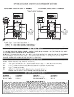
If wiring into a switched 120 VAC power source follow the AS2 connection diagram below. If using the optional FC24 Fan Center to
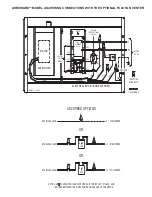
control the Aireshare by a 24 volt thermostat follow the FC24 wiring diagrams.
CAP
2.5 uF
CAP
6 uF
CAP
5 uF
8089034 10/27/14
MOTOR
AS2 BLOWER
AS2 ELECTRICAL BOX
CABLE
L1
60 Hz
120 VAC
N
GROUND
BLK
GRN
WIRE NUTS
= BY OTHERS
= SUPPLIED
BLK
BRN
GRN / YEL
120 VAC
1.0 AMPS @
SWITCH =
WHT
BLK
SPEED OPTIONS
SEE AS2
BELOW
L1 = HIGH SPEED
AS2 BLACK LEAD
L1 = MED SPEED
L1 = LOW SPEED
AS2 BLACK LEAD
AS2 BLACK LEAD
IS WIRED BETWEEN THE WHITE AND BROWN LEADS OF THE MOTOR.
NOTE:
OR
OR
AS2 SPEED OPTIONS
A 2.5 uF CAPACITOR IS ALWAYS USED ON THE 120 VAC "N" LEAD, AND
AIRESHARE
TM
MODEL AS2 WIRING CONNECTIONS
DIAGRAM N
ATTACH GRILLE TO WALL
WITH PROVIDED SCREWS.
DIAGRAM M
ATTACH J-BOX COVER TO
BLOWER J-BOX.
WARNING
!


