
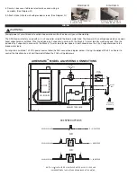
8089033 10/27/14
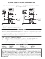
MOTOR
AS2 BLOWER
RED
YEL
BLK
WHT
XFORMER
20 VA
120 / 24
YEL
VIO
GRY
FC24
7
8
3
6
ELECTRICAL BOX (SHOWN EXPANDED)
CABLE
SPEED OPTIONS
SEE AS2
L1
60 Hz
120 VAC
N
BLK
WHT
CAP
2.5 uF
BLK
CABLE
GROUND
GRN / YEL
BRN
T-STAT
WIRING
SEE FC24
BLK
BLK
GRN
WIRE NUTS
= BY OTHERS
= SUPPLIED
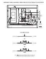
L1 = HIGH SPEED
AS2 BLACK LEAD
CAP
6 uF
CAP
5 uF
L1 = MED SPEED
L1 = LOW SPEED
AS2 BLACK LEAD
AS2 BLACK LEAD
A 2.5 uF CAPACITOR IS ALWAYS USED ON THE 120 VAC "N" LEAD, AND
IS WIRED BETWEEN THE WHITE AND BROWN LEADS OF THE MOTOR.
NOTE:
OR
OR
AS2 SPEED OPTIONS
BELOW
AIRESHARE
TM
MODEL AS2 WIRING CONNECTIONS WITH THE OPTIONAL FC24 FAN CENTER


