background image

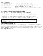
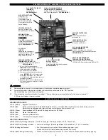
LED STATUS INDICATORS

LED #4 & #5 (Red) Flashing Alternately

=  Venter in Pre-purge. (Pre-Purge options 0, 5, 20, 35 seconds)

LED #4 & #5 (Red) Flashing in Unison

=  Venter in Post-Purge. (Post-Purge options 0, 30 seconds or 1, 2, 4, 8, 16 minutes)

LED #4 Flashes Continuously*

=  Fan Prover opened for more than 10 seconds during burner cycle.

(Venter will run for 10 minutes, attempting to make Fan Prover)

LED #5 (Red) Flashing Intermittently

=  With no call for heat, flashes 3 seconds on / 3 seconds off if microcontroller is working properly.

LED FAULT INDICATORS

Fault conditions are indicated by counting the number of times LED #4 (Red) flashes.
LED #4 Flashes 2 Times

Fan Prover was in electrically closed position prior to venter operation.

LED #4 Flashes 3 Times*

Fan Prover does not close within 60 seconds after call for heat.

LED #4 Flashes 4 Times*

Fan Prover did not re-close after 10 minutes of Venter operation.

LED #4 Flashes 5 Times*

Fan Prover opened for more than 10 seconds during burner cycle but closed within 10 minutes.

* Investigate cause of Fan Prover short cycling such as; Firing burner at capacities or temperatures exceeding Venter limits, 

excessive vent pipe runs, elbows directly on venter discharge, high winds, plugged / kinked Fan Prover sensing tube or a faulty 
Fan Prover switch.  In-Forcer model’s intake screen and prefilter, if applicable, should be cleaned if necessary.

CHECKING MEMORY FOR LAST FAULT CODE 
IMPORTANT:

Prior to accessing the fault code memory, note the settings of the dip switches so that they can be returned to their original Pre /

Post-Purge positions.  When power is supplied to the UC1 use caution when moving dip switches.
The last fault code can be retrieved at any time by setting all dip switches 1-8 to the up, or “on” position.  The last fault code, or lack there of, will
be indicated by counting the number of times LED 4 flashes.  By moving any of the dip switches back to their original position, the fault code will
be cleared.  

NOTE:

The UC1 board must have its 115 VAC power supply present when any of the (1-8) dip switches are moved back to their

original position for the fault code to clear.  

IMPORTANT:

Fault codes will automatically be displayed after a fault condition occurs. If the call for heat interlock signal

or 115 VAC power is removed, the UC1 board will reset and the fault will be stored in memory instead of displayed. Any
new fault will replace any previous fault.

Summary of Contents for SIDESHOT SS2

Page 1: ...eries Because of the low set point of the SS1 Fan Prover as low as 03 w c cross winds may cause the Fan Prover to close prior to a call for heat Activating the Prover Status Check on the SS1 may cause...

Page 2: ...es exceeding Venter limits excessive vent pipe runs elbows directly on venter discharge high winds plugged kinked Fan Prover sensing tube or a faulty Fan Prover switch In Forcer model s intake screen...

Page 3: ...G IN FIRE ELECTRICAL SHOCK CARBON MONOXIDE POISONING EXPLOSION PERSONAL INJURY OR PROPERTY DAMAGE NOTE Oil burner capacities exceeding 1 GPH may require the burner to be adjusted to more efficient 12...

Page 4: ...ipment to the outdoors By recirculating indoor air with a cooling fan surrounding com bustible materials remain at safe temperatures After each burner cycle the SS2 will continue to operate in post pu...

Page 5: ...be connected to a natural draft chimney 5 The SS2 shall not be installed where flue gas temperatures exceed 650oF 343oC at its inlet Flue gas temperature verification A On oil fuel verify flue gas te...

Page 6: ...OF A PREVIOUSLY USED APPLIANCE Perform prior to SS2 installation The following procedure is intended as a guide to aid in determining that an appliance is properly installed and is in safe condition...

Page 7: ...LIANCE INTERLOCK RELAY VENTER MOTOR RELAY A B 1 2 3 4 L N J1 J2 XL XN P1 P2 C GND F 1 9 N M MTR 4 C GND F AUXILIARY DEVICE COMMUNICATION TERMINALS 2 mA 5VDC For Tjernlund MAC1E or MAC4E auxiliary devi...

Page 8: ...ilure to do so may result in personal injury and or equipment damage LED 6 RED should not be on if 115 VAC supply power is removed from the control Pre purge Used for longer vent runs to get draft ful...

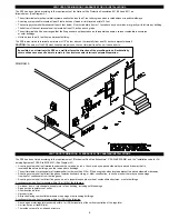
Page 9: ...code for Oil burning Equipment CSA Std B139 M91 See Diagram A1 A venting system shall not terminate underneath a veranda porch or deck or above a paved sidewalk or a paved driveway that is located bet...

Page 10: ...ng Saw SS2 VENT SYSTEM CLEARANCES FROM COMBUSTIBLES OBSTRUCTIONS With an inlet flue gas temperature of 650oF 343oC or below the SS2 has been Listed for Zero Clearance from combustibles NOTE You must a...

Page 11: ...r easy one person installations remove 3 screws from rear and bottom of vent cabinet Slide venter assembly out of SS2 cabinet and set aside being careful not to dam age housing After SS2 cabinet is se...

Page 12: ...apered reducers and increasers as shown below Determine vent pipe layout which will allow for the least amount of elbows to the appliance Calculate the equivalent vent pipe length from the appli ance...

Page 13: ...e to wire the SS2 as outlined in these instructions call Tjernlund s Customer Service Department toll free at 1 800 255 4208 for assistance IMPORTANT If the call for heat interlock signal or 115 VAC p...

Page 14: ...N 9183046 6 115 VAC LEGEND CALL JUMPER Ignitor CRIMP GROUND WIRE TO GROUNDING SPADE TERMINAL IN SS2 ELECTRICAL BOX IMPORTANT Line Voltage Thermostat or Aquastat Control Low Voltage Jumper 1 Separate t...

Page 15: ...D CALL JUMPER CRIMP GROUND WIRE TO GROUNDING SPADE TERMINAL IN SS2 ELECTRICAL BOX IMPORTANT Limit or Aquastat Control Low Voltage Jumper 1 Disconnect B1 from L1 of oil burner primary control burner re...

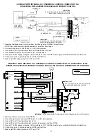
Page 16: ...sure RED voltage jumper on UC1 is on 115V SIDESHOT WITH INTEGRAL UC1 UNIVERSAL CONTROL CONNECTED TO AN OIL FIRED FURNACE WITH A HONEYWELL T87 OR EQUIVALENT NON POWERED THERMOSTAT XN R UNIVERSAL CONTR...

Page 17: ...ELECTRICAL BOX CRIMP GROUND WIRE TO GROUNDING SPADE TERMINAL IN IMPORTANT 1 Remove the wire on MV at gas valve and connect it on 1 on UC1 terminal block 2 Connect 2 on UC1 terminal block to MV PV 3 Co...

Page 18: ...resulting in fire carbon monoxide poisoning explosion personal injury or property damage 1 Insert a stack thermometer into the vent pipe as close as possible to the SS2 inlet NOTE plug hole when fini...

Page 19: ...he main burner is burning properly i e no floating lifting or flash back C If the heater has a two stage or modulating gas valve verify that burner operates properly at both low and high fire If the d...

Page 20: ...direct at 1 800 255 4208 for further assistance LED STATUS FAULT INDICATORS LED INDICATOR LIGHTS LED 1 Amber Appliance call for heat LED 2 Blue Safety circuit through P1 P2 SS2 Limit Fan Prover Indica...

Page 21: ...J2 on UC1 circuit board if using typical wiring where supply voltage from ter minal 1 is routed to terminal 3 through call jumper then to 4 when appliance interlock relay makes With call for heat esta...

Page 22: ...roubleshooting guide to determine defective component If unable to determine faulty component contact your Tjernlund distributor or Tjernlund Products Technical Customer Service Department at 1 800 25...

Reviews: