18
SYMPTOM 1: SS2 OPERATES CONTINUOUSLY
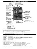
Verify that Venter is not in post-purge mode which could last up to 16 minutes. A factory post-purge has been set for 2 minutes. LED #4 & #5 (Red)
will flash in unison during post-purge. A Venter pre-purge could also be set for up to 35 seconds. LED #4 & #5 (Red) will flash alternately during pre-
purge. See “Pre / Post-Purge Settings” on page 5.
Verify that LED #1 (Amber) is not lit.
Yes, LED #1 (Amber) is lit: Check interlock wiring. Confirm burner control(s) are functioning properly. UC1 control is receiving constant call for heat signal.
LED #1 (Amber) is not lit: Replace UC1 circuit board part number 950-8804.
SYMPTOM 2: SS2 MOTOR AND/OR COOLING FAN DOES NOT OPERATE
Verify that UC1 control has power, LED #6 (Red) should be lit. Verify that LED #4 (Red) is not flashing. See “LED Status & Fault Indicators”, page 17.
Verify RED voltage selection jumper corresponds with interlock voltage (i.e 24V, 115V or “Dry”).
No: Check circuit breaker, disconnect switches and wiring. Confirm that Venter motor leads are connected to N & MTR terminals.
Yes, LED #6 (Red) is lit: Verify that the interlocked burner is calling for heat, LED #1 (Amber) should be lit.
No, LED #1 (Amber) is not lit: Verify interlock wiring and that thermostat/aquastat is adjusted to call for heat. Verify that the RED
voltage selection jumper is installed so that it matches the voltage of the interlocked burner.
Yes, LED #1 (Amber) is lit: Verify Prover safety circuit fault does not exist. See, “LED Status & Fault Indicators”, page 17.
If faults exist check Prover P1 & P2 safety circuit.
If no faults exist, check for 115 VAC across terminals N and MTR.
Voltage present: Confirm motor & cooling fan leads are securely on N and MTR. If so, replace SS2 motor p/n 950-0015 or SS2 cooling fan, p/n 950-0020.
No voltage present: Replace UC1 circuit board part number 950-8804.
SYMPTOM 3: SS2 OPERATES, BUT BURNER DOES NOT
Push reset button on SS2 high limit behind access cover underneath SS2 draft adjustment knob.
NOTE:
Insufficient post-purge may cause limit to trip.
If the limit switch trips, verify that the post-purge setting is long enough to remove residual heat from the combustion chamber. If high limit will not reset
and has an open circuit, replace high limit part number 950-0018. Verify that the cooling fan operates whenever the SS2 is running. If high limit trips
repeatedly, do not operate the heater until the source of excessive heat has been determined and repaired. For any newly established call for heat the
SS2 will run for 60 seconds to try to close the fan prover circuit (P1 to P2). If circuit can not be made after 60 seconds LED #4 (Red) will flash 3 times,
indicating a prover check circuit fault on UC1 start up.
NOTE:
The UC1 safety circuit and LED #4 will be reset if the call for heat interlock signal or 115
VAC power is removed. If the fan prover makes on start up, but breaks for more than 10 seconds during the burner cycle, LED #4 will flash continu-
ously indicating a prover circuit fault. The SS2 will continue to run for 10 minutes to try to make the prover circuit as long as a call for heat exists. If
Prover is not made within 10 minutes the SS2 will shut down and LED #4 will flash 4 times indicating a prover circuit fault. Remove the call for heat
and then reestablish to reset the UC1 prover safety circuit (P1 to P2) & LED #4.
Verify that LED #2 (Blue) is lit.
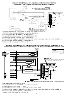
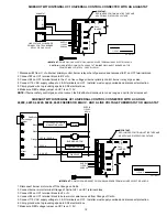
Yes, LED #2 (Blue) is lit: Verify that "call jumper" is connected from J1 to J2 on UC1 circuit board if using typical wiring where supply voltage from ter-
minal 1 is routed to terminal 3 through “call jumper” then to 4 when appliance interlock relay makes. With call for heat established, verify that wiring is
correct by measuring voltage between terminals 1 & 2 and 2 & 4 of UC1 terminal strip.
NOTE:
If a different voltage source is provided to terminal 3
which is switched to terminal 4 or when using the A-B dry contacts, voltage measurements may not apply. For millivolt installations make sure system
Limits are reset and relight pilot.
No, LED #2 (Blue) is not lit: Remove power from UC1 and push dip switch #9 up or “on” to deactivate Pre-Cycle Fan Prover status check. Remove
P1 and P2 prover leads off of Fan Prover switch and jumper together. Reset SS2 High Limit if not previously done. Reestablish power and call for
heat. After Venter pre-purge, if set (up to 35 seconds), LED #2 (Blue) should light.
No, LED #2 (Blue) does not light: Replace UC1 circuit board, part number 950-8804.
Yes, LED #2 (Blue) lights up: The Fan Proving switch may not be closing, SS2 High Limit may be tripped, wiring connections are incorrect/broken or
burner control(s) are not functioning properly. Push reset button on SS2 high limit behind access cover underneath SS2 draft adjustment knob.
NOTE:
Insufficient post-purge may cause limit to trip. If the limit switch trips, verify that the post-purge setting is long enough to remove residual heat from the
combustion chamber. Verify that the cooling fan operates whenever the SS2 is running. If high limit trips repeatedly, do not operate the heater until the
source of excessive heat has been determined and repaired. If high limit will not reset and has an open circuit, replace high limit part number 950-0018.
Verify inlet assembly sensing tube is clean. Verify fan proving switch flexible sensing tube is clean and not crimped or cracked. Remove two fan prover
switch retaining screws, disconnect sensing tube from the proving switch and connect sensing tube to draft gauge. Initiate call for heat. With SS2 run-
ning, verify that venter performance is sufficient to close fan prover. Draft gauge should read a minimum of -0.40" w.c. If draft gauge is unavailable,
verify that Venter performance is sufficient to close Fan Prover contacts by checking for continuity across switch.
IMPORTANT:
After continuity check
push dip switch #9 back down to “activate” Pre-Cycle Fan Prover status check. Replace Fan Prover leads from P1 and P2 back on Fan Proving switch.
No, measured draft is less than -0.40" w.c. or Prover contacts are not making: Verify that SS2 damper is completely open and visually inspect system
for blockages. Confirm that maximum BTU/hr. input, temperature and vent pipe lengths are not exceeded. See “Application Table” on page 1 for capacities.
Yes, measured draft is at least -0.40" w.c.: Replace fan proving switch, (
Old style
metal, exterior junction box mounted, p/n 950-0016)
(
New style
plastic, interior junction box mounted, p/n 950-0029). I
MPORTANT:
Old and new style Fan Provers are not interchangeable.
MAINTENANCE
INSTALLER AND USER REQUIREMENTS
•
Installer must visually inspect unit annually.
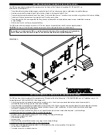
• On oil, installer must verify over-fire draft, CO2 and smoke readings are all correct. See “Draft Adjustment Procedure” on pages 15, 16.
• Inspect vent pipe for evidence of corrosion. If any corrosion is found replace vent pipe and inspect venter.
Disconnect power supply from the SS2 and heating equipment when making wiring connections and servicing the SS2.
Failure to do so may result in personal injury and/or equipment damage. LED #6 (RED) should be off with power removed.

