background image


Installation and User Manual


Product: 

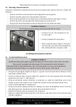
TJM Vehicle Mount Compressor 

Vehicle: 

Generic 

Part No.  

013COMPVHD 


For product warranty please refer to our website www.tjm.com.au 

File: F-17800.docx 

Page 1 of  12 

29/05/2019 


TJM Vehicle Mount Compressor


Before commencing fitment read instructions and ensure all listed components are supplied. 


It  is  a  condition  of  the  warranty  that  the  product  has  been  correctly  installed  by  suitably  qualified 
personnel  and  is  used  in  accordance  with  accompanying  instructions  where  provided.


For  product 

warranty please refer to our website www.tjm.com.au 


Estimated Fitting Time: 2 hrs 


Treat any holes drilled into the vehicle body with rust preventative paint. 


Always place the product on a soft workspace to prevent damage prior to installation. 


Do not mount compressor below the water-wading line of the vehicle. Refer to the vehicle manufacturer 
for this specification. 


Compressor  surface  becomes 

very  hot

  during  operation.  Mount  away  from  flammable  materials  and 

avoid locations where it may be accidently touched while operating. 


Rated for 12 V DC systems only. 
Summary of Contents for 013COMPVHD

Page 1: ...nd is used in accordance with accompanying instructions where provided For product warranty please refer to our website www tjm com au Estimated Fitting Time 2 hrs Treat any holes drilled into the veh...

Page 2: ...Post Installation Examination 9 6 0 Operating Instructions 9 7 0 Maintenance 11 1 0 Compressor Specifications 1 1 Bill of Material Item No QTY Part Number Description 1 1 F 17615 Compressor 2 1 013COM...

Page 3: ...screw Base plate to Vehicle Bolts Not Included 4 x M6 or M8 bolts and nuts 1 5 Recommended Fastener Torque Settings M5 9 5 Nm M6 16 Nm BSPT 15 Nm BSPT 20 Nm 2 0 Compressor Assembly 2 1 Accessory Insta...

Page 4: ...f the safety relief valve was removed apply sealant paste or sealant tape and re install the valve to the same port Notes DO NOT over tighten may cause damage to thread If using a thread sealant allow...

Page 5: ...placed Contact a TJM Distributor for service 3 0 Vehicle Mounting 3 1 Mounting Location When deciding an appropriate place to mount the compressor within the vehicle consider the following o Avoid pro...

Page 6: ...hers are fitted between the screw and rubber isolator o It is possible to undo the screws on one side of the compressor and rotate the body of the compressor to give better access to the base plate o...

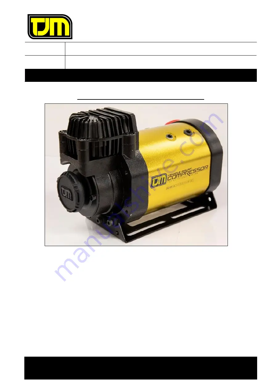
Page 7: ...iring System Installation Conditions Installation following this diagram requires the Rear Locker to be active to select the Front Locker This prevents unexpected handling changes from accidental Fron...

Page 8: ...ont Locker Solenoid o Plug the compressor motor connector into the Red White and Black loom connector o Fit ring terminals the ends of the Red and Black 10 AWG wires o Connect the red wire to the batt...

Page 9: ...bles will appear at the source of the leak o De pressurise the system o Re tighten the leaking fitting s and repeat leak test o If leaking continues remove fittings reapply sealant and then re assembl...

Page 10: ...alled o Never blow compressed air directly at people or pets Compressed air can blow dirt particles into the atmosphere which can irritate the skin eyes and or respiratory system o Do not use the comp...

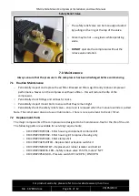
Page 11: ...ife of the compressor o Periodically check fittings and airlines for leaks o Periodically inspect mount bolts to ensure that they remain tight o Periodically check the safety relief valve ensure air i...

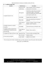
Page 12: ...blade fuse Relay blown Test with another relay and replace if required Faulty pressure switch Check for voltage at relay terminal 86 Replace switch if required Compressor switches on and off frequent...

Reviews: