TJM Vehicle Mount Compressor Installation and User Manual
For product warranty please refer to our website www.tjm.com.au
File: F-17800.docx
Page 7 of 12
29/05/2019
3.3
Mounting Actuator Switches
Compressor and Actuator switches should be mounted in a position best suited to the driver, consider the
following:
o
Switches must be hard mounted and never hanging from the wiring alone;
o
Switches should be easily seen and accessible to the driver;
o
Ensure that the switches are out of the way of accidental activation by passengers or driver;
o
Switches should be mounted away from potential exposure to water; and
o
Enough room should be left behind the mounting face to fit the switch and wiring.
Installation Conditions:
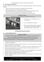
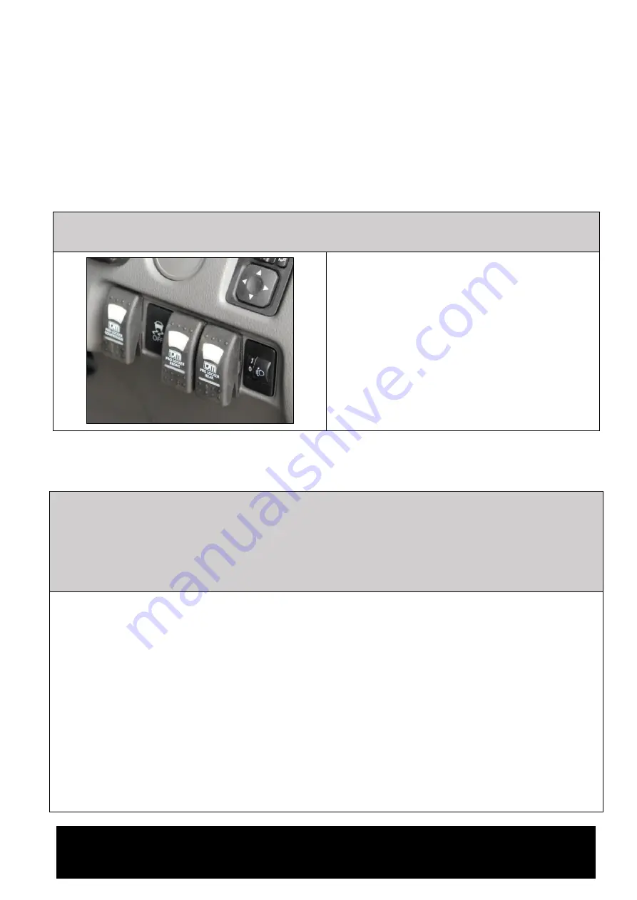
The Pro Locker actuator switches are supplied with the Pro Locker.
o
Create 21 mm x 41 mm rectangular cut-out
for each switch.
o
Securely snap switches into position.
o
When wired according to Figure 1, the switch
will illuminate Green when the dash lights are
ON, and Red when the compressor is ON.
4.0
Wiring the Compressor System
4.1
Connecting Wiring System
Installation Conditions:
Installation following this diagram requires the Rear Locker to be active to select the Front Locker.
This prevents unexpected handling changes from accidental Front Locker activation.
TJM recommends wiring the Red/12 V wire to the Ignition circuit to reduce likelihood of
compressor draining the battery. It is possible to wire to the Accessory circuit instead.
o
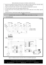
Using the wiring diagram depicted in Figure 1, plug the correct coloured female terminals to the
appropriate switch terminal.
o
Locate an accessory outlet or power outlet that supplies 12 V DC and is powered when the vehicle
ignition key in
the “ACC” or “ON” position.
o
Using an automotive quality connectors or soldering iron, splice the Red/Yellow wire to the
positive (+) wire on the chosen source. Insulate the connection to prevent possible short circuit.
o
Locate an active dash light 12 V supply wire.
o
Using an automotive quality connectors or soldering iron, splice the Blue/White wire to the active
dash light supply wire. Insulate the connection prevent possible short circuit.
o
Route the remainder of the wiring loom to the compressor.
o
Plug the 2, singular female flag-connectors to the pressure switch (the order of the connectors does
not affect operation).


