background image

Pilot Operating Handbook  


Section 4  

TL-2000  

Sting 


Normal Procedures 

Notice! The information contained in this document is for reference and information only. 

The pilot is the final and only responsible party for the safe operation of this aircraft. 


31 December 09 / Chg 5_____________________________________________14 

Copyright © 2009       Reproduction of this document or any of its parts is forbidden.


will cause the brake pads to glaze and the brake caliper to chatter with 

each brake application.   


Be sure to maintain hand control of the flight stick while taxiing.  This will 

prevent the elevator from jolting up and down when taxiing over bumps or 

dips. Ensure the compass heading is swinging and in the proper 

direction.  When in taxi turns, observe the turn coordinator.  The display 

should indicate the direction of the turn and the ball should be free to 

move in the race. 


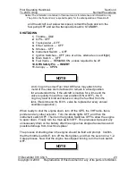
ENGINE RUN-UP 

1. 

Brakes  --  HOLD 

2. 

Oil Temperature  --  110°F min. 

3. 

Oil Pressure  --  29 – 73 PSI 

4. 

Cylinder Head Temperature  --  110º F min.  

5. 

Throttle  --  4000 RPM 

6. 

Ignition Switches  --  300 RPM DROP (max), 120 RPM DIFF (max)  

7. 

Throttle  --  2000 RPM    

8. 

Fuel Pressure  --  CHECK 

9.  GRS Safety Pin –


Check Removed 


Hold the brakes before beginning the engine run-up.  Ensure that both the oil 

temperature, oil pressure, and cylinder head temperatures are within their 

respective tolerances.  The following process should be accomplished quickly 

yet fluidly to avoid overheating the engine or possibly pulling debris into the 

propeller.   


The brakes may not hold the aircraft during high power settings. 

Therefore, do not taxi up close to the restricted runway hold line 

prior to ignition check.  Remain clear of the runway environment 

during the time that attention is diverted into the cockpit for engine 

observations. 


Smoothly apply adequate throttle to stabilize at 4000 RPM.  Turn off the first 

ignition switch and note the RPM on the EMS.  Turn the first ignition back on 

and allow the RPM to return to the higher setting.  Immediately turn off the 

second ignition switch and note the RPM on the EMS.  Then turn the second 

NOTE 


Summary of Contents for Sting TL-2000 2009

Page 1: ...ference and information only The pilot is the final and only responsible party for the safe operation of this aircraft 31 December 2009 Change 5 Copyright 2009 Reproduction of this document or any of...

Page 2: ...tion 0 TL 2000 Sting Introduction Notice The information contained in this document is for reference and information only The pilot is the final and only responsible party for the safe operation of th...

Page 3: ...lying and enjoyment With this Pilot Operating Handbook POH we hope to help inform you about the design and operation of your aircraft This Pilot Operating Handbook is to be used as a guide to assist t...

Page 4: ...ation contained in this document is for reference and information only The pilot is the final and only responsible party for the safe operation of this aircraft 31 December 09 Chg 5 ii Copyright 2009...

Page 5: ...afe operation of this aircraft 31 December 09 Chg 5 iii Copyright 2009 Reproduction of this document or any of its parts is forbidden SECTION INDEX SECTION GENERAL 1 OPERATING LIMITATIONS 2 EMERGENCY...

Page 6: ...conditions steps in a procedure helpful hints or useful advice This text box represents danger to equipment or operation By not observing the cautions the result could be the destruction of equipment...

Page 7: ...to by the operator or pilot in command PIC Each aircraft is issued an FAA form 8050 15 which is a statement identifying the specific ASTM standard used in design and manufacture of that seral aircraft...

Page 8: ...2 31 09 4 6 12 31 09 4 7 12 31 09 4 8 12 31 09 4 9 12 31 09 4 10 12 31 09 4 11 12 31 09 4 12 12 31 09 4 13 12 31 09 4 14 12 31 09 4 15 12 31 09 4 16 12 31 09 4 17 12 31 09 4 18 12 31 09 4 19 12 31 09...

Page 9: ...ft 31 December 09 Chg 5 ____________________vii Copyright 2009 Reproduction of this document or any of its parts is forbidden List of changes CHG NR REVISED DATE REVISED PAGES EXTENT OF REVISION CHANG...

Page 10: ...ined in this document is for reference and information only The pilot is the final and only responsible party for the safe operation of this aircraft 31 December 09 Chg 5 ____________________viii Copy...

Page 11: ...ion of this document or any of its parts is forbidden SECTION 1 GENERAL INFORMATION TABLE OF CONTENTS Page THREE VIEW DRAWINGS Sting S3 1 2 THREE VIEW DRAWINGS Sting Sport 1 3 INTRODUCTION 1 4 DESCRIP...

Page 12: ...tained in this document is for reference and information only The pilot is the final and only responsible party for the safe operation of this aircraft 31 December 09 Chg 5 1 2 Copyright 2009 Reproduc...

Page 13: ...cument is for reference and information only The pilot is the final and only responsible party for the safe operation of this aircraft 31 December 09 Chg 5 1 3 Copyright 2009 Reproduction of this docu...

Page 14: ...hich are included with the aircraft Any conflicts found in these supplier manuals are superseded by the appropriate OEM manufacturer s POH or AMM manuals The Sting is has a high cruising speed and may...

Page 15: ...aximum Takeoff or Landing Weight 1320 Lbs Standard Empty Weight 780 Lbs Maximum Useful Load 540 Lbs Total Baggage Weight 60 Lbs Each baggage compartment can hold a maximum of 20 Lbs An additional 20 L...

Page 16: ...RPM and may not allow a safe takeoff Loading the engine with a high propeller pitch angle high propeller angle of attack AOA or big angle above 21 5 may also result in may result in extremely long tak...

Page 17: ...an be filled with approximately 21 5 gallons of fuel This will eliminate all fuel expansion area as the fuel expands it will be forced out of the fuel vent line and spill on to the parking area causin...

Page 18: ...ecured against an abrupt movement Do not allow baggage to block the exit area of the aircraft parachute system nor hinder free deployment of the parachute riser cables After securing baggage assure th...

Page 19: ...Flight VH The highest speed that can be attained in level flight at sea level under standard conditions while the engine is operating at the manufacturer designated maximum continuous power setting N...

Page 20: ...el 91 Octane is min auto gas rating for Rotax engines Avgas 100 Octane Low Lead Aviation Fuel 100LL Max 30 use in Rotax Ballast A specific amount of weight attached in a specific location which can be...

Page 21: ...datum for the Sting Demonstrated Crosswind Velocity The velocity of the crosswind component at which adequate control of the airplane was actually demonstrated during takeoff and landing certification...

Page 22: ...un up fuel Maximum Takeoff Weight The maximum weight at which an airplane is approved for the start of its takeoff roll Moment The product of the weight of an item multiplied by its arm distance from...

Page 23: ...p Weight Basic Empty Weight Useful Load The useful load will be reduced by the installation of additional equipment Usable Fuel The amount of fuel available for engine use in flight Unusable Fuel The...

Page 24: ...e ASTM Standards Datum Location base for measurement s DC Direct Current DOT Department of Transportation US EIS Engine Information System EFIS Electronic Flight Information System EMS Engine Monitori...

Page 25: ...nots True Kg Kilogram KM Kilometer Kt Knot nautical mile Lb s Pound s LL Low Lead as in 100LL LSA Light Sport Aircraft LSP Light Sport Plane M Meter MAC Mean Aerodynamic Chord MAG Magnetic slang engin...

Page 26: ...orbidden PSI Pounds per Square Inch RPM Revolutions per Minute STRB Strobe switch STRT Start switch T B Turn and bank indicator Tach Tachometer TC Turn Coordinator TCP Fuel Additive Tri Cresyl Phospha...

Page 27: ...aircraft 31 December 09 Chg 5 2 1 Copyright 2009 Reproduction of this document or any of its parts is forbidden SECTION 2 OPERATING LIMITATIONS TABLE OF CONTENTS Page INTRODUCTION 2 AIRSPEED LIMITATI...

Page 28: ...on IFR operations See page 2 7 for further details AIRSPEED LIMITATIONS V SPEED KIAS KCAS REMARKS VNE Never Exceed Speed 164 162 Do not exceed this speed in any operation VNO Maximum Structural Cruisi...

Page 29: ...one Takeoff Approach setting Green Arc 44 118 43 117 Normal Operating Range Lower limit is maximum weight VS at most forward CG with flaps retracted Upper limit is maximum structural cruising speed VC...

Page 30: ...acturer s manual supplied with the aircraft for more detailed Rotax engine data Engine Manufacturer Rotax G m b H Aircraft Engines Engine Model Number 912 UL or ULS 914UL Maximum Power 80 100 or 115 B...

Page 31: ...ation time by the engine manufacturer If 91 Octane Unleaded is not available during travel adding 100LL Avgas in any proportion to partial tanks of 91 Unleaded is acceptable Following use of Avgas dur...

Page 32: ...n a higher cruise speed may cause the engine RPM to bog down fail to reach a sufficient ground RPM and will not allow a safe takeoff Loading the engine with a high propeller pitch high propeller angle...

Page 33: ...ation not necessary for normal flight FLIGHT LOAD FACTOR LIMITS Flight Load Factors Flaps Up 4g 2g Flaps Down 4g 2g FLIGHT LIMITATIONS The Sting is certified only for VFR VMC or IFR VMC flight conditi...

Page 34: ...cument or any of its parts is forbidden Limited IFR IMC operations may be approved by the OEM manufacturer for specific aircraft meeting appropriate ASTM FAA standards Such operations will continue to...

Page 35: ...ILURES 5 ENGINE FAILURE DURING TAKEOFF ABORT 5 ENGINE FAILURE LANDING IMMEDIATELY AFTER TAKEOFF 6 ENGINE FAILURE DURING FLIGHT 6 FORCED LANDINGS 7 EMERGENCY LANDING WITHOUT ENGINE POWER 7 PRECAUTIONAR...

Page 36: ...rmation contained in this document is for reference and information only The pilot is the final and only responsible party for the safe operation of this aircraft 31 December 09 Chg 5 __ 3 2 Copyright...

Page 37: ...ion should be considered and applied as necessary to correct the problem Due to the fact that emergencies can occur at any altitude or any moment procedures to follow may have to be suitably altered b...

Page 38: ...y the Galaxy High Technology GRS Corporation It is imperative that the owner pilot of this airplane read and understand the system operating manual provided by Galaxy In most emergency scenarios the u...

Page 39: ...a nose low attitude and sufficient airflow over the control surfaces exists limited control in flight may be accomplished If this is possible make every effort to guide the airplane toward an isolated...

Page 40: ...Switch OFF The aircraft is capable of very high takeoff climb deck angles or AOA at low speeds Loss of engine power will result in loss of airspeed very quickly due to the nose high attitude Be prepar...

Page 41: ...e the auxiliary fuel pump is ON for takeoff Ensure that both ignition switches are on and then engage the starter button If the engine still will not start complete the forced landing procedures detai...

Page 42: ...anding Do not dive toward the landing zone if at too high an altitude in order to attempt a safe landing Doing so will result in a high energy high speed approach that is not likely to allow the aircr...

Page 43: ...st Even though it may be possible to obtain a higher speed than VG do not fly the airplane faster This procedure will provide the maximum travel distance If the engine can produce sufficient thrust ma...

Page 44: ...down procedures Add Full flaps and establish a steady slow 200fpm descent rate at an airspeed of 55 KIAS This is done to allow for a slow airspeed with a slow descent rate prior to the water surface i...

Page 45: ...r OBTAIN 11 Airplane EVACUATE 12 Fire Extinguisher USE AS REQUIRED 13 Airplane INSPECT FOR DAMAGE If a fire occurs while starting the engine continue to crank the engine to attempt to draw the fire ba...

Page 46: ...y DIVE the aircraft to a lower altitude to minimize the time for the fire to spread within the cockpit 1 Fuel Valve OFF 2 Throttle FULL OPEN 3 Aux Fuel Pump OFF 4 Ignition Switches OFF 5 Cabin Heat OF...

Page 47: ...ransponder to alert ATC of the emergency Proceed with the forced landing that has been established ELECTRICAL FIRE IN FLIGHT 1 Main Switch OFF 2 All Switches Except Ignition Switches OFF 3 Cabin Heat...

Page 48: ...s turned on Be prepared for an emergency landing and land as soon as possible If you choose to troubleshoot any problem when airborne remember that the main priority in any airborne situation is to fl...

Page 49: ...en damaged consider using a smooth sod runway if available Touchdown on the undamaged gear first This can be accomplished by using aileron to bank into the good gear and using opposite rudder to keep...

Page 50: ...raft to maintain 70 KIAS 6 Upon re entering VFR VMC conditions resume normal cruise operation Close the throttle to prevent any further increase in airspeed produced by the engine Because it presents...

Page 51: ...Should an inadvertent spin occur in this airplane the following recovery procedure should be used 1 Throttle IDLE 2 Ailerons NEUTRALIZE 3 Rudder APPLY FULL in opposite direction of rotation 4 Elevator...

Page 52: ...turning each ignition switch OFF and then back ON one at a time An obvious power loss in single ignition operation is evidence of spark plug or ignition module trouble If the problem persists proceed...

Page 53: ...E reduce power and speed immediately Do not attempt abrupt control movement or unusual attitudes Continue flight using minimum safe speed and control pressures to land as soon as possible After landin...

Page 54: ...ircraft 31 December 09 Chg 5 __ 3 20 Copyright 2009 Reproduction of this document or any of its parts is forbidden vibration if it is a wheel spinning The nose wheel may also rotate and vibrate above...

Page 55: ...its parts is forbidden SECTION 4 NORMAL PROCEDURES TABLE OF CONTENTS Page INTRODUCTION 3 AIRSPEEDS FOR NORMAL OPERATION 3 PREFLIGHT INSPECTION 3 COCKPIT 3 EXTERIOR CHECKLIST 4 NOSE AREA 4 RIGHT WING 6...

Page 56: ...this document is for reference and information only The pilot is the final and only responsible party for the safe operation of this aircraft 31 December 09 Chg 5______________________________________...

Page 57: ...Design Cruise Speed VC 95 115 KIAS Landing and Approach Flaps Up Emergency only 70 KIAS Flaps Half Normal for all approaches 60 KIAS Flaps Full Normal for all landings 55 KIAS Balked Landing Maximum...

Page 58: ...l panel indicator located on the instrument panel to determine the ELT s status Cross check this status with the actual ELT by removing the passenger seat back to locate the ELT Ensure the ON ARMED OF...

Page 59: ...ne should only use a small amount of oil during normal operation For longer flights it may be advisable to add oil until it reaches its maximum limit on the dipstick to allow for some oil consumption...

Page 60: ...eel in either direction Comply with proper environmental fuel disposal regulations and do not dump fuel onto the ground When draining the fuel sump always use a clean clear fuel sampler Pour clean fue...

Page 61: ...screws that fasten the wheel pant bracket to the gear assembly should all be tight Confirm that the grounding wire attached inboard to the right gear assembly is securely fastened It should make suffi...

Page 62: ...ttempt to move the rudder The rudder is directly connected to the nose wheel so there will only be slight rudder travel The horizontal stabilizer and trim tab should also be free of cracks and punctur...

Page 63: ...are operational Inspect the wing s leading edge for flaws or damage These can impede smooth airflow over the wing The bolt and two screws that fasten the wheel pant bracket to the gear assembly shoul...

Page 64: ...canopy remains unattended unlocked open in the wind or during taxi operations 2 Harnesses ADJUST and FASTEN 3 Headsets ON and ADJUST 4 All Switches OFF 5 Fuel Valve ON 6 Throttle IDLE 7 Main Switch ON...

Page 65: ...nition The choke is by passed and will not be activated at high RPM throttle positions Open the fuel valve and momentarily turn on the auxiliary fuel pump to pump fuel into the engine The fuel pump wi...

Page 66: ...warm up and then try closing the choke again Always be observant of the oil pressure temperature and cylinder head temperatures on the EMS data display during engine operation PRE TAXI 1 Oil Pressure...

Page 67: ...latch to exit the cockpit Allow a minimum of two minutes for the engine to warm up sufficiently prior to engine run up in order to stabilize internal engine temperatures This can include time during...

Page 68: ...min 3 Oil Pressure 29 73 PSI 4 Cylinder Head Temperature 110 F min 5 Throttle 4000 RPM 6 Ignition Switches 300 RPM DROP max 120 RPM DIFF max 7 Throttle 2000 RPM 8 Fuel Pressure CHECK 9 GRS Safety Pin...

Page 69: ...should be determined BEFORE TAKEOFF 1 Harnesses SECURE 2 Loose Items SECURE 3 Instruments CHECK and SET 4 EMS Data CHECK 5 VHF Radio SET 6 Transponder ON ALT 7 Trim AFT 8 Flaps HALF 9 Controls FREE an...

Page 70: ...igh engine temperatures and cause the engine to fail on full throttle application Watch for erratic rpm or rough operation when increasing the throttle Auto fuel vapor lock is the result of seasonal o...

Page 71: ...runway Maintain elevator back pressure and when clear for takeoff add enough power to just get the airplane moving As the airplane steadily accelerates smoothly add full power As airspeed increases r...

Page 72: ...re gravity fed They will automatically feed as the main tank is depleted The main tank will continue to indicate FULL for the time that the aux tanks are draining If installed the aux wing tank pumps...

Page 73: ...rnesses SECURE 2 Airspeed 75 KIAS 3 Fuel CHECK QUANTITY 4 Secure Loose Items 5 Aux Fuel Pump ON 6 Strobe Lights ON Prior to entering the traffic pattern ensure that the seat belts and shoulder harness...

Page 74: ...pe On final approach 6 Airspeed 60 KIAS 7 Flaps FULL 8 Trim AFT AS REQUIRED 9 Throttle IDLE or as required 10 Airspeed 55 KIAS on short final 11 Touchdown MAIN WHEELS FIRST NOSE HIGH 12 Braking MINIMU...

Page 75: ...y breaking may cause exceptionally fast tire and brake wear and may result in a tire failure CROSSWIND LANDING If a strong crosswind exists during landing it is practical to use the minimum flap setti...

Page 76: ...tive rate stabilized climb 2 Flaps SET TO HALF 3 Airspeed 50 KTS VX 4 Flaps RETRACT WHEN CLEAR OF OBSTACLES 5 Airspeed 55 KTS VY 6 If a go around is executed full power should be applied a climb at VX...

Page 77: ...hut Off Valve may attach to the metal of the valve stem if allowed to remain in a fixed position for an extended time If the aircraft is inactive for a time and the valve is quickly moved to a new pos...

Page 78: ...headsets reinsert the GRS safety pin into the activation handle When opening the canopy reverse your method of the closing sequence It is imperative that the GRS safety pin be reinserted into its resp...

Page 79: ...he pilot is the final and only responsible party for the safe operation of this aircraft 31 December 09 Chg 5 5 1 Copyright 2009 Reproduction of this document or any of its parts is forbidden SECTION...

Page 80: ...tion contained in this document is for reference and information only The pilot is the final and only responsible party for the safe operation of this aircraft 31 December 09 Chg 5 5 2 Copyright 2009...

Page 81: ...eoff Distance Over a 50ft Obstacle 9400 Ft Max power Half flaps paved runway RATE OF CLIMB Rate of Climb 810FPM at 55Kts VY Max power Half flaps CRUISE SPEED Design Cruise Speed 95 115 KIAS Maximum Cr...

Page 82: ...tion contained in this document is for reference and information only The pilot is the final and only responsible party for the safe operation of this aircraft 31 December 09 Chg 5 5 4 Copyright 2009...

Page 83: ...2009 Reproduction of this document or any of its parts is forbidden SECTION 6 WEIGHT BALANCE INFORMATION TABLE OF CONTENTS Page INTRODUCTION 3 STANDARD INSTALLED EQUIPMENT LIST 3 AUXILIARY ITEMS 4 WEI...

Page 84: ...information contained in this document is for reference and information only The pilot is the final and only responsible party for the safe operation of this aircraft 31 December 09 Chg 5 6 2 Copyrig...

Page 85: ...WER PORT 2 AUXILIARY 12V EXTERNAL POWER CONNECTION AUXILIARY ENGINE FUEL PUMP AUX AUXILIARY WING FUELTANKS FILTER PUMP If Installed CABIN HEAT SYSTEM CARGO BAGGAGE BOXES 2 EMERGENCY LOCATOR TRANSMITTE...

Page 86: ...result from specific weights and forces anticipated to occur in normal operations within its specified flight envelope An aircraft s handling qualities and structural integrity may be seriously compr...

Page 87: ...aximum and Minimum Weights Due to certain balance structural and aerodynamic considerations sometimes a manufacturer may specify maximum or minimum weights for certain locations on the aircraft For ex...

Page 88: ...alled must also be listed Ballast A specific amount of weight attached in a specific location which can be temporarily or permanently installed in an aircraft to help bring its CG within the required...

Page 89: ...easurements For best results weigh indoors The scales must be calibrated correctly and must be set on level ground Any equipment placed on the scales when weighing the aircraft such as chocks or block...

Page 90: ...ocation 66498 Total Moment 805 Empty Weight 82 6 inches aft of Datum Plane Figure 6 1 Example of Initial Empty Weights LOADED WEIGHT AND BALANCE CALCULATIONS Complete the Loaded CG calculations as was...

Page 91: ...omplete this chart for each of critical test loading conditions to be sure that your final Loaded CG position falls within the allowable CG limits at all times for all operations CRITICAL LOADING COND...

Page 92: ...performing the calculation An entry moment arm is included in the sample should any changes be made to the instrument panel This document in its entirety becomes a part of the Aircraft Legal Document...

Page 93: ...contained in this document is for reference and information only The pilot is the final and only responsible party for the safe operation of this aircraft 31 December 09 Chg 5 6 11 Copyright 2009 Rep...

Page 94: ...4 2 30803 Right Gear 326 94 2 30709 Empty A C 805 82 6 66498 Instrument Changes 59 5 Main Fuel 120 68 4 8208 Wing Fuel 0 80 1 0 Pilot 1 195 90 1 17570 Pilot 2 175 90 1 15768 Baggage 25 117 0 2925 Tota...

Page 95: ...Item Weight Arm Moment Nose Wheel 32 8 Left Gear 94 2 Right Gear 94 2 __________ Empty A C Instrument Changes 59 5 Main Fuel 68 4 Wing Fuel 80 1 Pilot 1 90 1 Pilot 2 90 1 Baggage 117 0 __________ Tota...

Page 96: ...information contained in this document is for reference and information only The pilot is the final and only responsible party for the safe operation of this aircraft 31 December 09 Chg 5 6 14 Copyrig...

Page 97: ...ON 3 AIRFRAME 3 FLIGHT CONTROLS 3 TRIM SYSTEM 4 GROUND CONTROL 4 INSTRUMENT PANEL 4 WING FLAP SYSTEM 5 LANDING GEAR 6 SAFETY HARNESSES 6 CANOPY 7 ENGINE 7 ENGINE CONTROLS 7 ENGINE INSTRUMENTS 8 ENGINE...

Page 98: ...ation contained in this document is for reference and information only The pilot is the final and only responsible party for the safe operation of this aircraft 31 December 09 Chg 5 ______ 7 2 Copyrig...

Page 99: ...the wing tip and is about a foot longer The area of both wings is exactly the same The wings are attached to the fuselage by two interlocking box type spars that cross beneath the cockpit and interlo...

Page 100: ...is operated by two control rods connected between each of the rudder pedals to either side of the nose wheel hinge The rudder and nose wheel steering operate as follows to turn left the left pedal is...

Page 101: ...ON light VHF radio and transponder Along the base of the center panel are the starter push button guarded left and right ignition switches guarded main and instrument switches a guarded strobe light s...

Page 102: ...nd the right toe pedal will actuate the right main landing gear brake SAFETY HARNESSES Each seat in the aircraft is equipped with a four point safety harness Each of the shoulder harnesses is latched...

Page 103: ...powered by a normally aspirated liquid air cooled gear reduced drive dual carburetor equipped four cylinder four stroke horizontally opposed Rotax 912UL S engine and is rated at 80 100 BHP at 5800 RP...

Page 104: ...ed the EMS will alert with a light or change color to illuminate affected display If installed a difference of as much as 200 RPM can exist between the Rotax tachometer and the RPM indication on the E...

Page 105: ...in isolating engine deficiencies Starter operation is controlled by a momentary push button The starter solenoid is then energized which in turn activates the starter AIR INDUCTION EXHAUST SYSTEM Unli...

Page 106: ...ith a small starting carburetor commonly referred to as a choke for starting Starting a cold engine may be difficult and the cylinders may need more fuel than air to burn A starting carburetor is used...

Page 107: ...n requires it to be off The fuel shut off can remain in the ON position to prevent damage of the rubber O ring by quick rotation Fuel will not drain overboard with the fuel shut off in the ON position...

Page 108: ...sion To break the siphon open the main tank cap lock lever don t remove the cap and raise the nose by pushing down on the tail area ahead of the vertical fin Do not sit on the horizontal tail surfaces...

Page 109: ...ntained in this document is for reference and information only The pilot is the final and only responsible party for the safe operation of this aircraft 31 December 09 Chg 5 ______ 7 13 Copyright 2009...

Page 110: ...pull knob is located forward of the left pilot s armrest which is connected to the vent by a Bowden cable control wire By pulling the knob aft the vent opens to close the vent push the knob forward Wa...

Page 111: ...ned in this document is for reference and information only The pilot is the final and only responsible party for the safe operation of this aircraft 31 December 09 Chg 5 ______ 7 15 Copyright 2009 Rep...

Page 112: ...t and left vertical surface of each seat The pilot side port is directly hot wired to the battery and can be used to charge the battery without the pilot having to connect additional leads directly to...

Page 113: ...nd decreased drag The center panel has a STRB ON OFF circuit breaker switch CBS for the strobe lights Night lighting for the instruments is provided and dimmable Internal lighting of the cockpit is pr...

Page 114: ...As altitude decreases the aneroid wafers will contract Atmospheric pressure is supplied to the altimeter by the static ports on the pitot tube or aft on the fuselage Mechanical linkages attached to th...

Page 115: ...he transponder contains a computerized altimeter connected to the pitot static system that allows it to calculate the aircraft s altitude This data is then transmitted to the ground radar of ATC This...

Page 116: ...ation contained in this document is for reference and information only The pilot is the final and only responsible party for the safe operation of this aircraft 31 December 09 Chg 5 ______ 7 20 Copyri...

Page 117: ...s for reference and information only The pilot is the final and only responsible party for the safe operation of this aircraft 31 December 09 Chg 5 8 1 Copyright 2009 Reproduction of this document or...

Page 118: ...information contained in this document is for reference and information only The pilot is the final and only responsible party for the safe operation of this aircraft 31 December 09 Chg 5 8 2 Copyrig...

Page 119: ...ds and markings located inside the cockpit and on the exterior of the airplane These placards and markings provide guidance instruction or caution It is the responsibility of the owner pilot to unders...

Page 120: ...f this aircraft 31 December 09 Chg 5 8 4 Copyright 2009 Reproduction of this document or any of its parts is forbidden Aux wing fuel tank filler neck rims FUEL CAPACITY 6 US GALLONS Main landing gear...

Page 121: ...formation only The pilot is the final and only responsible party for the safe operation of this aircraft 31 December 09 Chg 5 8 5 Copyright 2009 Reproduction of this document or any of its parts is fo...

Page 122: ...rmation only The pilot is the final and only responsible party for the safe operation of this aircraft 31 December 09 Chg 5 8 6 Copyright 2009 Reproduction of this document or any of its parts is forb...

Page 123: ...Copyright 2009 Reproduction of this document or any of its parts is forbidden SECTION 9 AIRPLANE HANDLING SERVICE MAINTENANCE TABLE OF CONTENTS Page INTRODUCTION 3 AIRPLANE FILES 3 AIRPLANE INSPECTION...

Page 124: ...e The information contained in this document is for reference and information only The pilot is the final and only responsible party for the safe operation of this aircraft 31 December 09 Chg 5 9 2 Co...

Page 125: ...Pilot Operating Handbook POH 2 Weight and Balance Data 3 Operating Limitations issued by FAA at airworthiness inspection 4 Aircraft Airworthiness Certificate FAA Form 8130 7 5 Aircraft Registration Ce...

Page 126: ...he best precaution to prevent damage Metal screw rings are located underneath each wing tip for fastening tie down straps or ropes The nose gear can be tied down by attaching a rope or strap around an...

Page 127: ...ted with leaded Avgas fuels The lead contained in Avgas will deposit in the piston rings and in the rocker arms of the valve train Use Avgas only while traveling when unleaded fuel is not available Wh...

Page 128: ...aded unleaded fuel SHELL Advance VSX 4 APISG SAE 15W 50 Semi synthetic motorcycle oil w gear additives for normal high temps leaded unleaded fuel SHELL Advance Ultra 4 APISJ SAE 10W 40 Full synthetic...

Page 129: ...s leaded unleaded fuel SHELL Formula Shell APISJ SAE 10W 30 Petroleum based oil for normal temps leaded fuel only SHELL Formula Shell APISJ SAE 20W 50 Petroleum based oil for normal temps leaded fuel...

Page 130: ...ated at the rear of the firewall Remove the dipstick to check the oil level A flattened segment at the end of the dipstick represents the oil capacity range The top of this segment is the MAX limit an...

Page 131: ...engine oil before installation To ensure a better seal rub fresh oil around the sealing ring of the new oil filter 8 Snuggly screw on new oil filter by hand Turn until hand tight and the seal is comp...

Page 132: ...is a waterless coolant and may not be recognized by line personnel prior to the addition of water to top off the system To add engine coolant 1 Remove the cap and inner screen of the coolant system s...

Page 133: ...torage Run the engine long enough on Avgas to fill the carb bowls before storage TIRE PRESSURES Nose Wheel Tire Pressure 30 psi 2 bar Main Gear Wheel Tire Pressure 30 psi 2 bar CLEANING AND CARE CANOP...

Page 134: ...electric problems Check coolant brake fluid and engine oil levels to determine if there are any losses Clean the radiator vanes from bugs and debris using a low pressure water hose and a cloth Never...

Page 135: ...mber 09 Chg 5 10 1 Copyright 2009 Reproduction of this document or any of its parts is forbidden SECTION 10 SUPPLEMENTARY INFORMATION TABLE OF CONTENTS Page INTRODUCTION 3 FAMILIARIZATION FLIGHT PROCE...

Page 136: ...information contained in this document is for reference and information only The pilot is the final and only responsible party for the safe operation of this aircraft 31 December 09 Chg 5 10 2 Copyrig...

Page 137: ...attering noise if you unintentionally ride the brakes while taxiing It is an irritant not a serious problem and can be fixed by removing the pads and scrubbing them with a file to remove the glaze Use...

Page 138: ...er the nose if the engine performance diminishes It is better to climb at a higher speed than a lower speed for safety So don t continue a Vy climb any longer than necessary to clear any obstacle Main...

Page 139: ...in that situation and plan the decent to remain well below Vne If you anticipate the descent you will also be in a good position to handle any turbulence at a reasonable airspeed that is not high int...

Page 140: ...turns you have to make If you find that you are overshooting the final approach course don t tighten the turn just continue the turn through the runway heading to an intercept angle from the other sid...

Page 141: ...t the Sting will continue to fly well below the speed of the approach and flare You will be using that difference in speed energy to maneuver the plane during the last few inches above the runway The...

Page 142: ...ent at some uncontrolled runways does not allow direct vision of all the exit taxiways from the runway hold position PARKING As in the taxi for takeoff do not let the ground speed increase as you retu...

Page 143: ...tall and the other will continue to produce lift The result can be a roll into the stalled wing that is initially disturbing to new pilots because the large canopy gives you no sense of enclosure Do n...

Page 144: ...RECOVERY ON LANDING Occasionally an airplane will bounce when forced into a hard landing The primary concern after an initial bounce on the runway is to recover go around and attempt a second landing...

Page 145: ...and information only The pilot is the final and only responsible party for the safe operation of this aircraft 31 December 09 Chg 5 10 11 Copyright 2009 Reproduction of this document or any of its pa...

Page 146: ...Ignition OFF 2 Harnesses TIGHTEN 3 GRS Activation Handle PULL FIRMLY 25 POUNDS 4 Radio SET TO 121 5 TRANSMIT MAYDAY MAYDAY MAYDAY with AIRCRAFT ID and CURRENT POSITION 5 Transponder SET TO 7700 6 Gli...

Page 147: ...O 7700 7 Landing Zone CIRCLE OVER if possible BEFORE LANDING 8 All Switches OFF 9 Harnesses TIGHTEN 10 Flaps FULL on final 11 Touchdown PREFERABLY INTO WIND NOSE HIGH 12 Brakes APPLY AS REQUIRED PRECA...

Page 148: ...EVACUATE 13 Anticipate that the aircraft may be inverted FIRES ENGINE FIRE DURING START 1 Starter CONTINUE CRANKING If engine starts 2 Power 2000 RPM for a few seconds 3 Fuel Valve OFF 4 Engine SHUTD...

Page 149: ...inues 7 Land ASAP If fire appears out and electrical power is necessary for extended flight 8 Main Switch OFF 9 All Switches Except Ignition Switches OFF 10 Circuit Breakers CHECK for faulty circuit d...

Page 150: ...T Control Panel Indicator CHECK STATUS 6 Main Switch OFF 7 Flight Controls PROPER OPERATION 8 Flaps PROPER OPERATION SET FULL 9 Trim CENTERED 10 Required Documentation ON BOARD 11 Baggage SECURED 12 S...

Page 151: ...LATION and WEAR 9 Chock REMOVE 10 Wing Leading Edge CHECK 11 Wing Aux Tank if installed CHECK QUANTITIY FUEL TYPE 12 Wing Aux Tank Cap SECURE 13 Under wing Inspection Ports SECURE CHECK CONTINUITY 14...

Page 152: ...CONTINUITY 7 Wing Aux Tank if installed CHECK QUANTITIY FUEL TYPE 8 Wing Aux Tank Cap SECURE 9 Gear Leg and Brake Line CHECK 10 Wheel Pant and Bracket SECURE 11 Brake Pads and Disk CHECK FOR WEAR 12 T...

Page 153: ...Safety Pin REMOVED and STOWED TAXI 1 Area CLEAR 2 Brakes CHECK and APPLY AS NEEDED 3 Steering CHECK 4 Compass CHECK 5 attitude reference Track Display CHECK 6 Turn Coordinator CHECK in turns 7 GRS Sa...

Page 154: ...ps RETRACT SMOOTHLY AT 500 AGL CLIMB 1 Throttle SET TO 5500 RPM or as required 2 Climb 75 KIAS 3 Trim ADJUST AS NEEDED 4 EMS Data CHECK 5 Aux Fuel Pump ON CRUISE 1 Throttle 5200 TO 5400 RPM 2 Trim LEV...

Page 155: ...9 Throttle IDLE or as required 10 Airspeed 55 KIAS on short final 11 Touchdown MAIN WHEELS FIRST NOSE HIGH 12 Braking MINIMUM BALKED GO AROUND LANDING 1 Throttle FULL 2 Flaps SET TO HALF 3 Airspeed 5...

Page 156: ...information contained in this document is for reference and information only The pilot is the final and only responsible party for the safe operation of this aircraft 31 December 09 Chg 5 10 22 Copyri...

Reviews: