10
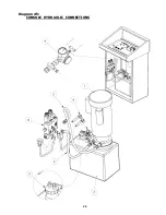
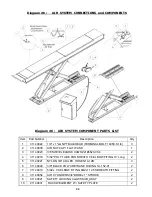
(iii) Connect passenger side safety lock air line
(5/32” blue tubing)
to “T” fitting from accessory
box. Connect driver side safety lock air line
(5/32” blue tubing)
to “T” fitting. Connect “T”
fitting to air solenoid in console using
5/32”
blue tubing from accessory box.
(iv) Connect rolling air/hydraulic jacks air line from lift to console
(if optional rolling jacks were purchased)
(rolling jacks must be installed with air lines connected to the lift before turning on the air)
NOTE : All electrical wiring other than low voltage (24 volts or less) should be
performed by a certified electrician.
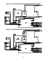
(v) Low Voltage Linear Transducer Connections
– 1
cable from runway #1 and 1 cable from runway #2
Do not proceed with low voltage electrical connections at this time
. The lift
must first be cycled up and down several times
(step #11)
to remove air pockets before
connecting these cables. Low voltage electrical connection is step #16.
7. Fill oil reservoir with hydraulic oil
(ISO 32)
.
8. Connect operator console or control pendant to electrical service
(should be performed by a certified electrician).
9 . Lift operation controls on the console perform the following functions:
- "RAISE" button raises the lift. "LOWER" button lowers the lift. Note: Pressing the "lower" button
will first raise the lift slightly to clear the safety locks and then proceed down to desired height.
- "ALIGNMENT LEVEL" button lowers the lift into safety locks for alignment purposes. Note: The
"alignment level" button and the "lower" button must be pressed at the same time to lower
and level the lift on the safety locks.
- "EMERGENCY STOP" button
stops the lift from being raised or lowered.
Note
: Always lock both slip plates and turnplates following alignment adjustments and before
removing vehicle from the lift.
10. Press the "UP" button and raise the lift 18 inches from the floor. Press the "DOWN"
button and lower the lift down to the floor. Check hydraulic oil level in operator console
reservoir and top up if required. Check all hydraulic and air lines to insure no leaks.
11. Press the "UP" button and raise the lift 36 inches from the floor. Press the "DOWN"
button and lower the lift down to the floor. Press the "UP" button and raise the lift
60 inches from the floor. Insure the safety locks under both runway assemblies are
engaging properly when the lift is being raised.
12.
Important: Before proceeding, confirm that all safety locks are totally engaged.
Dependable performance and accurate alignment results require a precisely leveled lift.
Take special care to complete the following leveling process: Check both base frames with
a 4 ft. level and identify the highest point. The leveling process will raise lower points on
both base frames to match
(or be level with)
the high point you identify. Using preinstalled
adjustment bolts located at the front and rear of each base frame, proceed to raise the
low points on each base frame to match
(or be level with)
the highest point you identified.
(reference diagram #9 for correct level measurement sequence)
Note: adjustment bolts cannot be used to support the lift when in use. They
are only used during the leveling process.
After the base frame has been leveled,
c
onfirm that both raised runway surfaces are also
level front to back and side to side.
Grout thickness
(measured from the floor to the bottom edge of a base frame)
cannot exceed
1½ inches. Confirm this maximum limit is not exceeded by taking measurements at one
foot intervals around both base frames. If you measure a distance greater than 1½ inches
stop the installation and call the manufacturer at 1 - 866 - 799 - LIFT
(5438).
The manufacturer will advise you how to proceed
(grout installation is step #14)
.
Installation Instructions continued on page 11


