8
TOOLS REQUIRED and PRE INSTALLATION PROCEDURES
Tools Required:
25ft. Measuring Tape
Chalk Line and Chalk
Side Cutters (tin snips)
Floor Jacks – 2 (or engine crane)
Crow Bar
Metric and SAE Wrenches and Ratchet Sets
Metric and SAE Allen Key Sets
Hammer
Screwdrivers
4 ft. Level (and laser level)
Rotary Hammer Drill
¼ inch and ¾ inch diameter Masonry Drill Bits
Grout – 1 pail purchased locally (
see last page of this manual for reference information
)
Trowel, Float and Mixing Pail for hydraulic grout
Pre Installation Procedures
Before proceeding with installation, read the installation manual and insure all instructions
are fully understood and all component parts are accounted for.
IMPORTANT:
DO NOT CUT THE SHIPPING STRAPS HOLDING EACH RUNWAY
ASSEMBLY TOGETHER UNTIL INSTRUCTED TO DO SO
(step 3
– page 9)
.
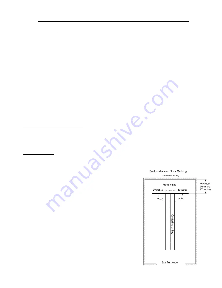
1. Identify bay center line near the front and mark the floor.
Also mark the center of bay entrance door. Connect
these two points with a chalk line. Locate the position
for front of the lift and draw a second chalk line at 90°
to the centerline
(this will be used to position the fronts of
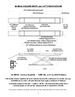
both runway assemblies - refer to lift dimensions on page 7).
2. At the front, measure 20 inches out from either side
of the centerline and mark the floor. Near where the
rear of the lift will be, measure 20 inches out from
either side of the centerline and mark the floor. Using
these marks draw two parallel chalk lines the length of
the lift
(these will be used to position the inside edge of each
base frame).
Pre Installation Instructions continued on page 9


