EF200R-C
4
Function and system design
Measuring principle
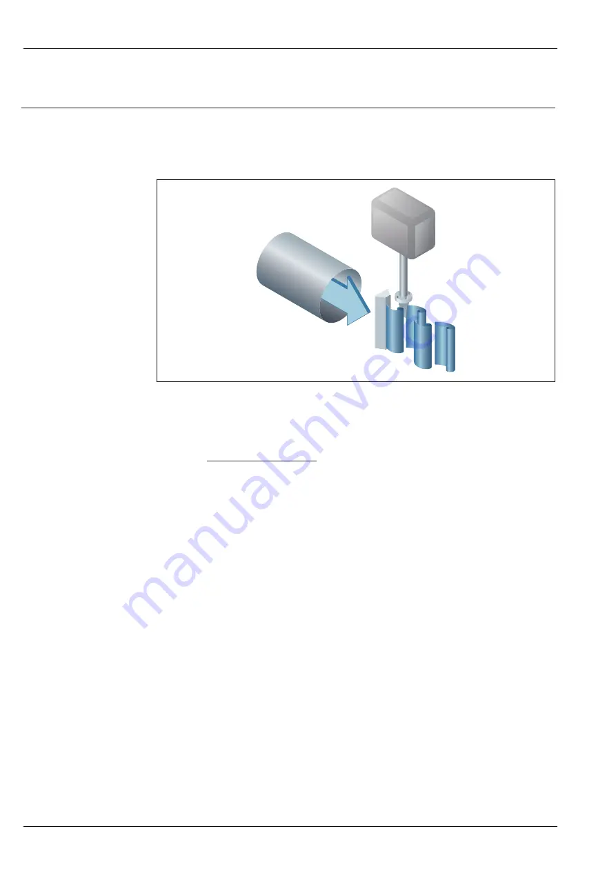
Vortex meters work on the principle of the
Karman vortex street
. When fluid flows past a bluff body,
vortices are alternately formed on both sides with opposite directions of rotation. These vortices each
generate a local low pressure. The pressure fluctuations are recorded by the sensor and converted to
electrical pulses. The vortices develop very regularly within the permitted application limits of the
device. Therefore, the frequency of vortex shedding is proportional to the volume flow.
A0033465
Sample graphic
The calibration factor (K-factor) is used as the proportional constant:
K-Factor =
Pulses
Unit Volume [m³]
Within the application limits of the device, the K-factor only depends on the geometry of the device.
It is for Re > 10
000:
• Independent of the flow velocity and the fluid properties viscosity and density
• Independent of the type of substance under measurement: steam, gas or liquid
The primary measuring signal is linear to the flow. After production, the K-factor is determined in
the factory by means of calibration. It is not subject to long-time drift or zero-point drift.
The device does not contain any moving parts and does not require any maintenance.
The capacitance sensor
The sensor of a vortex flowmeter has a major influence on the performance, robustness and
reliability of the entire measuring system.
The robust DSC sensor is:
• burst-tested
• tested against vibrations
• tested against thermal shock (thermal shocks of 150 K/s)
The measuring device uses the tried-and-tested, capacitance measuring technology,
which is already in use in over 450
000 measuring points worldwide. Thanks to its
design, the capacitance sensor is also particularly mechanically resistant to temperature shocks
and pressure shocks in steam pipelines.


