background image


9

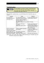
Troubleshooting 


When disassembling or removing the product, wait until the internal 

pressure equals atmospheric pressure and the surface of the product 

has cooled to room temperature. Disassembling or removing the 

product when it is hot or under pressure may lead to discharge of fluids, 

causing burns, other injuries or damage.


CAUTION


If the trap fails to operate properly, use the following table to locate the cause and 
remedy. 

Problem Cause  Remedy 

The trap operating pressure 
exceeds the maximum specified 
pressure or there is insufficient 
pressure differential between the 
trap inlet and outlet 

Compare specifications and 
actual operating conditions 

The piping is clogged with rust and 
scale 

Clean the piping 

The capacity of the trap is 
insufficient 

Compare specifications and 
actual operating conditions 

No condensate is 
discharged (blocked) or 
discharge is poor 
 

Steam-locking has occurred 

Perform a bypass blowdown or 
close the trap inlet valve and 
allow the trap to cool 

Improper installation orientation 

Correct the installation 

Steam is discharged or 
leaks from the outlet 
(blowing) (steam leakage) 

Trap vibration   

Lengthen the inlet piping and 
fasten it securely 

Steam is leaking from a 
place other than the outlet 

The outside of the trap has 
sustained damage 

Replace with a new trap 

Float becomes damaged 

Water hammer has occurred 

Study and correct the piping 


NOTE: SS3N 

 SS3V / SS5N 

 SS5V / SS5NH 

 SS5VH steam traps are of all-welded, single unit 

construction, so they cannot be repaired. 

172-65119MAJ-03 (SS3/SS5)  25 Feb 2014


Summary of Contents for SS3N

Page 1: ... SS3 SS5 25 February 2014 ISO 9001 ISO 14001 Manufacturer Kakogawa Japan is approved by LRQA LTD to ISO 9001 14001 Free Float Steam Trap SS3N SS3V SS5N SS5V SS5NH SS5VH Copyright 2014 by TLV CO LTD All rights reserved ...

Page 2: ... float steam trap uses a precision polished float and three point support for the valve body With no hinges or levers the trap automatically continuously discharges condensate preventing it from collecting The three point seating for the valve body supports the precision polished float securely at three points and ensures a high degree of sealing for even minute quantities of condensate If detaile...

Page 3: ...or serious injury WARNING Indicates that there is a potential threat of death or serious injury CAUTION Indicates that there is a possibility of injury or equipment product damage CAUTION Install properly and DO NOT use this product outside the recommended operating pressure temperature and other specification ranges Improper use may result in such hazards as damage to the product or malfunctions ...

Page 4: ...ry due to malfunction or the discharge of fluids CAUTION Use only under conditions in which no freeze up will occur Freezing may damage the product leading to fluid discharge which may cause burns or other injury Use only under conditions in which no water hammer will occur The impact of water hammer may damage the product leading to fluid discharge which may cause burns or other injury 172 65119M...

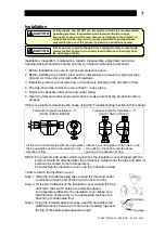
Page 5: ...has a check valve TLV CK been installed 5 Is the inlet pipe as short as possible with as few bends as possible and installed so the liquid will flow naturally down into the trap 6 Has the piping work been done correctly as shown in the figures below Requirement Correct Incorrect Install catchpot with the proper diameter Diameter is too small Make sure the flow of condensate is not obstructed Diame...

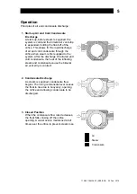
Page 6: ...ischarge of initial air and cold condensate the heat of the inflowing steam and condensate cause the bimetal air vent strip to contract 2 Condensate Discharge As steam is supplied condensate flow begins The rising condensate level causes the float to rise due to buoyancy opening the orifice and allowing condensate to be discharged 3 Closed Position When the condensate flow rate decreases the float...

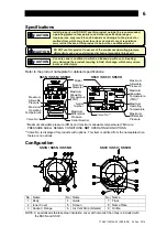
Page 7: ...ns SS3N SS5N SS5NH SS3V SS5V SS5VH Valve No Serial Number Model Nominal Diameter Maximum Allowable Pressure Maximum Operating Temperature Maximum Allowable Temperature TMA Maximum Differential Pressure Maximum Allowable Pressure Maximum Operating Temperature Maximum Allowable Temperature TMA Valve No Serial Number Maximum Differential Pressure Maximum allowable pressure PMA and maximum allowable t...

Page 8: ... functions properly If there is a problem determine the cause using the Troubleshooting section in this manual Tolerance Angle for Installation 5 SS3N SS5N SS5NH Tolerance Angle for Installation 5 SS3V SS5V SS5VH Install on a horizontal pipe with the nameplate facing upwards and the arrow pointing in the direction of flow Install on a verticle pipe with the inlet on top the outlet on the bottom an...

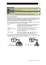
Page 9: ...may cause damage to piping and equipment resulting in faulty or low quality products or losses due to steam leakage Normal Condensate is discharged continuously together with flash steam and the sound of flow can be heard If there is very little condensate there is almost no sound of flow Blocked Discharge Impossible No condensate is discharged The trap is quiet and makes no noise and the surface ...

Page 10: ...ping is clogged with rust and scale Clean the piping The capacity of the trap is insufficient Compare specifications and actual operating conditions No condensate is discharged blocked or discharge is poor Steam locking has occurred Perform a bypass blowdown or close the trap inlet valve and allow the trap to cool Improper installation orientation Correct the installation Steam is discharged or le...

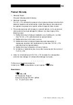
Page 11: ...by other than TLV CO LTD authorized service representatives 2 Malfunctions due to dirt scale rust etc 3 Malfunctions due to improper disassembly and reassembly or inadequate inspection and maintenance by other than TLV CO LTD authorized service representatives 4 Malfunctions due to disasters or forces of nature 5 Accidents or malfunctions due to any other cause beyond the control of TLV CO LTD 4 U...

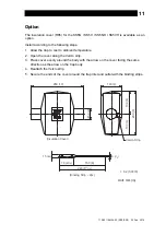
Page 12: ...pen the cover along the Velcro strip 3 Place cover evenly around the body with the arrow on the cover facing the same direction as the arrow on the trap body 4 Reattach the Velcro strip 5 Secure the ends of the cover around the trap inlet and outlet with the binding strips 15 5 8 250 10 100 4 φ50 2 100 4 100 4 200 8 150 6 70 23 4 220 811 16 6 1 4 Insulation Cover Velcro Strip Binding Strip 2pc t 0...

Reviews: