
172-65167MA-10 (VA1/VA3/VA4/VA5) 1 Oct 2021
9
Disassembly/Reassembly
NEVER apply direct heat to the float.
The float may explode due to increased internal pressure, causing accidents
leading to serious injury or damage to property and equipment.
Use hoisting equipment for heavy objects (weighing approximately 20 kg
(44 lb) or more).
Failure to do so may result in back strain or other injury if the object should fall.
When disassembling or removing the product, wait until the internal
pressure equals atmospheric pressure and the surface of the product has
cooled to room temperature.
Disassembling or removing the product when it is hot or under pressure may
lead to discharge of fluids, causing burns, other injuries or damage.
Be sure to use only the recommended components when repairing the
product, and NEVER attempt to modify the product in any way.
Failure to observe these precautions may result in damage to the product or
burns or other injury due to malfunction or the discharge of fluids.
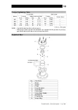
Use the following procedures to remove components. Use the same procedures in
reverse to reassemble.
(Installation, inspection, maintenance, repairs, disassembly, adjustment and valve
opening/closing should be carried out only by trained maintenance personnel
.
)
Dissassembly/Reassembly Procedure
Part
During Disassembly
During Reassembly
Cover Bolt 5
Remove with a socket wrench
Consult the table of tightening torques
and tighten to the proper torque
Cover 2
Lift off to remove
Make sure there are no pieces of the old
gasket left on the sealing surfaces and
reattach
Cover Gasket 4
Remove the gasket and clean
sealing surfaces
Replace with a new gasket
Set Screw 8
Remove with a Philips
screwdriver
Consult the table of tightening torques
and tighten to the proper torque
Valve Seat Holder
7
Remove, take care as it may
come with the valve seat
Attach making certain that the valve
seat is in the proper position
Valve Seat 6
Remove, being careful not to
scratch the sealing surface
Replace with a new valve seat if
misshapen or damaged
Float 3
Remove, being careful not to
scratch the polished surface
Insert, being careful not to scratch the
polished surface
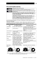
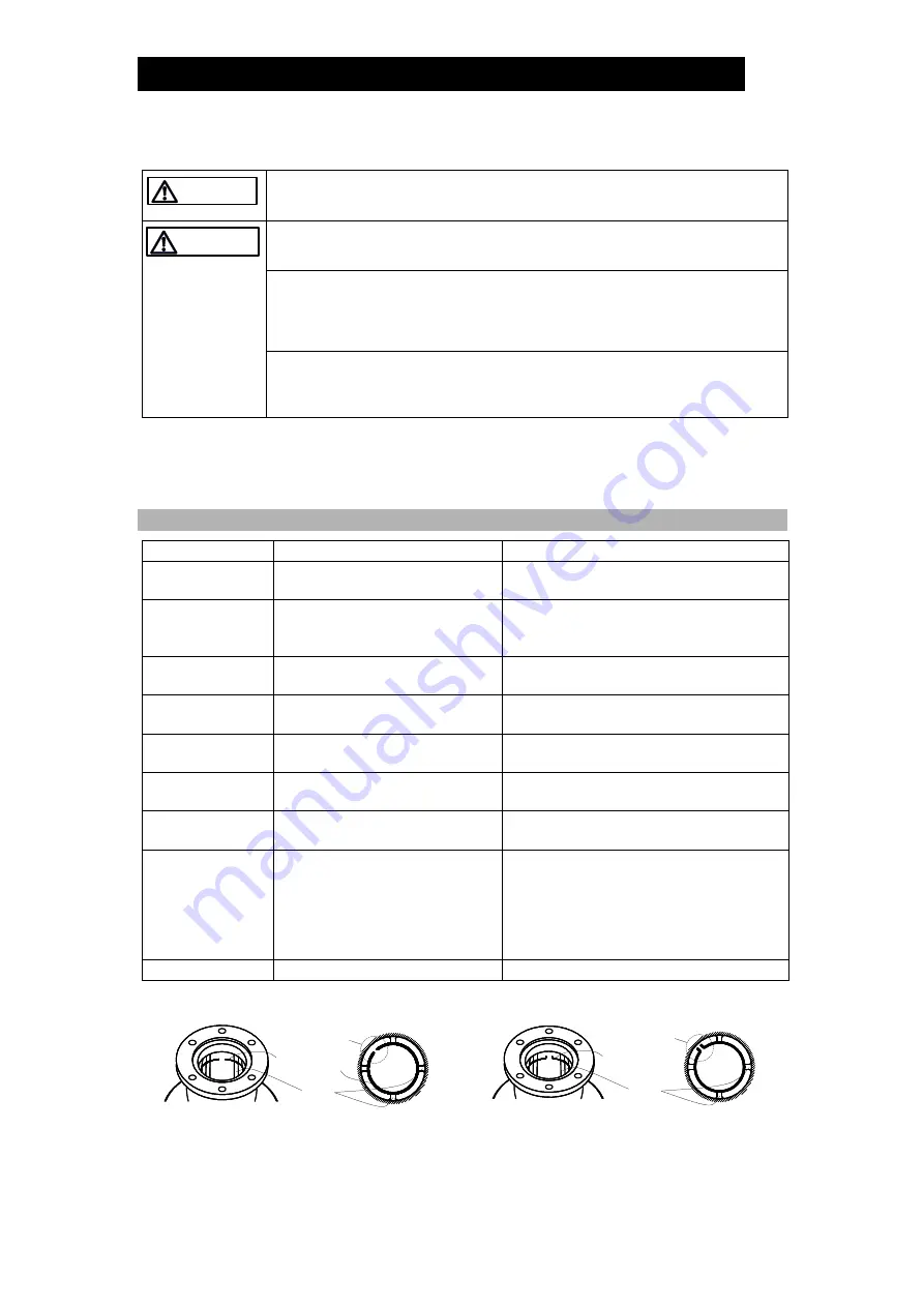
Snap Ring 10
VA1: With long-nose pliers,
grasp an end and pull away
from the groove and up
VA3/VA4/VA5: With long-nose
pliers, grasp both ends and pull
away from groove and up
Insert securely into the groove
Make sure that the ends of the snap ring
are set between ribs
(Figure A)
Float Guide 9
Remove without misshaping
Insert, being careful not to misshape
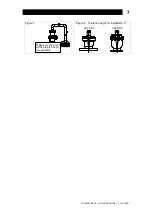
Figure A
VA1
VA3 / VA4 / VA5
NOTE: When inserting the snap ring into the groove on the rib inside the body, make sure
that the both ends of the snap ring are set between ribs.
WARNING
CAUTION
Snap Ring
Ends
Rib
Overhead View
Snap Ring
Ends
Rib
Overhead View


