background image


172-65167MA-10  (VA1/VA3/VA4/VA5)    1  Oct  2021


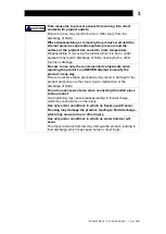
Disassembly/Reassembly


NEVER apply direct heat to the float.   

The float may explode due to increased internal pressure, causing accidents 
leading to serious injury or damage to property and equipment. 


Use hoisting equipment for heavy objects (weighing approximately 20 kg 
(44 lb) or more).   

Failure to do so may result in back strain or other injury if the object should fall.


When disassembling or removing the product, wait until the internal 
pressure equals atmospheric pressure and the surface of the product has 
cooled to room temperature.   

Disassembling or removing the product when it is hot or under pressure may 
lead to discharge of fluids, causing burns, other injuries or damage.


Be sure to use only the recommended components when repairing the 
product, and NEVER attempt to modify the product in any way.   

Failure to observe these precautions may result in damage to the product or 
burns or other injury due to malfunction or the discharge of fluids.


Use the following procedures to remove components. Use the same procedures in 
reverse to reassemble.   
(Installation, inspection, maintenance, repairs, disassembly, adjustment and valve 
opening/closing should be carried out only by trained maintenance personnel

.

)


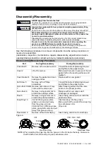
Dissassembly/Reassembly Procedure 


Part 

During Disassembly 

During Reassembly 

Cover Bolt 5 

Remove with a socket wrench 

Consult the table of tightening torques 
and tighten to the proper torque 

Cover 2 

Lift off to remove 

Make sure there are no pieces of the old 
gasket left on the sealing surfaces and 
reattach 

Cover Gasket 4 

Remove the gasket and clean 
sealing surfaces 

Replace with a new gasket   

Set Screw 8 

Remove with a Philips 
screwdriver 

Consult the table of tightening torques 
and tighten to the proper torque 

Valve Seat Holder 

Remove, take care as it may 
come with the valve seat 

Attach making certain that the valve 
seat is in the proper position 

Valve Seat 6 

Remove, being careful not to 
scratch the sealing surface 

Replace with a new valve seat if 
misshapen or damaged   

Float 3 

Remove, being careful not to 
scratch the polished surface 

Insert, being careful not to scratch the 
polished surface 

Snap Ring 10 

VA1: With long-nose pliers, 
grasp an end and pull away 
from the groove and up 
VA3/VA4/VA5: With long-nose 
pliers, grasp both ends and pull 
away from groove and up   

Insert securely into the groove 
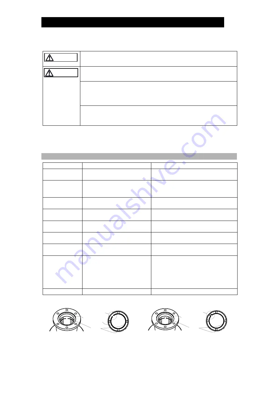
Make sure that the ends of the snap ring 
are set between ribs 
(Figure A) 

Float Guide 9 

Remove without misshaping 

Insert, being careful not to misshape 

Figure A 

VA1 

VA3 / VA4 / VA5 


NOTE: When inserting the snap ring into the groove on the rib inside the body, make sure 

that the both ends of the snap ring are set between ribs. 


WARNING 


CAUTION 

Snap Ring

Ends

Rib

Overhead View

Snap Ring

Ends

Rib

Overhead View

Summary of Contents for VA1

Page 1: ...172 65167MA 10 VA1 VA3 VA4 VA5 1 October 2021 Rapid Initial Air Vent VA1 VA3 VA4 VA5 Copyright 2021 by TLV CO LTD All rights reserved ...

Page 2: ... discharging the air initially present when supplying water to piping then closing upon completion of discharge During operation once it has closed the rapid initial air vent remains closed as long as there is internal pressure If air venting is necessary during system operation install an automatic air vent as well When draining piping the rapid initial air vent automatically opens to introduce a...

Page 3: ...of death or serious injury Indicates that there is a potential threat of death or serious injury Indicates that there is a possibility of injury or equipment product damage DO NOT use for toxic flammable or otherwise hazardous fluids This product is an air vent that discharges air from water piping system Use only for water and or air This product is for intended use only Improper use may result i...

Page 4: ...nded components when repairing the product and NEVER attempt to modify the product in any way Failure to observe these precautions may result in damage to the product and burns or other injury due to malfunction or the discharge of fluids Do not use excessive force when connecting threaded pipes to the product Over tightening may cause breakage leading to fluid discharge which may cause burns or o...

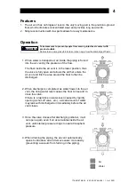
Page 5: ... position thus the valve is fully open and allows the air that enters the air vent and fills the area around the float to then be discharged 2 When discharge is completed as water flows into the air vent the rising water level causes the float to rise and to close the valve If there is a rapid rise in water level caused by rapidly opening a shut off valve etc a small amount of water may leak with ...

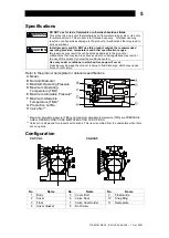
Page 6: ... below the conditions quoted Use only under conditions in which no freeze up will occur Freezing may damage the product leading to fluid discharge which may cause burns or other injury Refer to the product nameplate for detailed specifications A Model B Nominal Diameter C Maximum Operating Pressure D Maximum Operating Temperature TMO E Maximum Allowable Pressure F Maximum Allowable Temperature TMA...

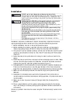
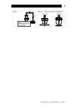
Page 7: ...lation be sure to remove all protective seals 2 Before installing the product open the inlet valve and blow out the piping to remove any piping scraps dirt and oil Close the inlet valve after blowdown 3 This product must be installed vertically with the inlet at the bottom and the outlet at the top and should be inclined no more than 5 horizontally and front to back Figure 2 4 Install the product ...

Page 8: ...172 65167MA 10 VA1 VA3 VA4 VA5 1 Oct 2021 7 Figure 1 Figure 2 Tolerance Angle for installation 5 VA1 VA3 VA4 VA5 Make sure the end of the pipe is above the waterline ...

Page 9: ... to water flow Normal Air is discharged as it accumulates with the air vent closing with no leakage when no air is present in the piping Blocked Discharge Impossible No air is discharged though air accumulates in the air vent NOTE Once the air vent closes it will remain closed until internal pressure drops to near or below atmospheric pressure This condition may be confused with a malfunction bloc...

Page 10: ...dure Part During Disassembly During Reassembly Cover Bolt 5 Remove with a socket wrench Consult the table of tightening torques and tighten to the proper torque Cover 2 Lift off to remove Make sure there are no pieces of the old gasket left on the sealing surfaces and reattach Cover Gasket 4 Remove the gasket and clean sealing surfaces Replace with a new gasket Set Screw 8 Remove with a Philips sc...

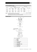
Page 11: ...32 0 5 0 37 VA4 80 59 24 15 16 0 8 0 59 VA5 200 150 36 113 32 6 4 4 1 N m 10 kg cm NOTE Coat all threaded portions with anti seize If drawings or other special documentation were supplied for the product any torque given there takes precedence over values shown here Exploded View No Part Name 1 Body 2 Cover 3 Float 4 Cover Gasket 5 Cover Bolt 6 Valve Seat 7 Valve Seat Holder 8 Set Screw 9 Float Gu...

Page 12: ...th dirt or foreign matter Clean the valve seat The inlet or outlet piping is clogged Clean the piping Water leaks when the vent is closed There is a build up of rust or scale on the valve seat or the valve seat is damaged Clean or replace with a new valve seat The float is misshapen dirty or has a film build up Clean or replace with a new float The installation angle of inclination is incorrect Co...

Page 13: ... TLV group companies or 6 improper storage maintenance or repair or 7 operation of the Products not in accordance with instructions issued with the Products or with accepted industry practices or 8 use for a purpose or in a manner for which the Products were not intended or 9 use of the Products in a manner inconsistent with the Specifications or 10 use of the Products with Hazardous Fluids fluids...

Page 14: ...EFECTIVE PRODUCT INJURY TO OTHER PROPERTY DAMAGE TO BUYER S OR THE FIRST END USER S PRODUCT DAMAGE TO BUYER S OR THE FIRST END USER S PROCESSES LOSS OF USE OR OTHER COMMERCIAL LOSSES WHERE DUE TO OPERATION OF LAW CONSEQUENTIAL AND INCIDENTAL DAMAGES UNDER THIS WARRANTY UNDER ANY OTHER EXPRESS WARRANTY NOT NEGATED HEREBY OR UNDER ANY IMPLIED WARRANTY NOT NEGATED HEREBY INCLUDING THE IMPLIED WARRANT...

Page 15: ...ks Road Nunawading Victoria 3131 Australia Tel Fax 61 0 3 9873 5610 61 0 3 9873 5010 In East Asia 36 Kaki Bukit Place 02 01 02 Singapore 416214 Tel Fax 65 6747 4600 65 6742 0345 Room 5406 No 103 Cao Bao Road Shanghai China 200233 Tel Fax 86 0 21 6482 8622 86 0 21 6482 8623 No 16 Jalan MJ14 Taman Industri Meranti Jaya 47120 Puchong Selangor Malaysia Tel Fax 60 3 8065 2928 60 3 8065 2923 252 94 K L ...

Reviews: