Installing Your External Cordless Adapter
Step 4: Set Right DIP Switches to Proper Positions
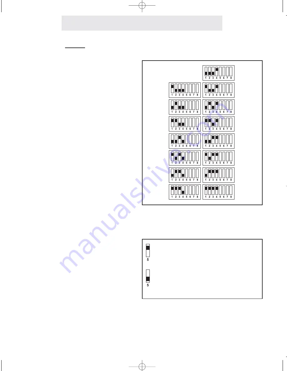
Set Switches 1-4
The setting of these four DIP switches
determines what station number your
External Cordless Adapter will be set as.
You may choose any station number from
12 to 26. Note that you may not set your
External Cordless Adapter as station #11.
Also please note that you must not assign
your External Cordless Adapter the same
station number as any of your phones or
other feature modules. IT MUST BE
ASSIGNED ITS OWN UNIQUE STATION
NUMBER.
Refer to the drawing at right to determine
how to set the DIP switches for the station
number you choose.
Set Switch 5
The setting of this DIP switch determines
flash length.
Set the switch in the up position for normal
length flashes (approximately 700 mil-
liseconds), or place the switch in the down
position for short flashes (approximately
200 milliseconds).
In most environments it is best to leave
this switch in the up position, for normal
length flashes. If you find that calls are
dropping when you use the flash button,
then try setting the switch in the down
position.
Set switch 5 in the up position to set
this External Cordless Adapter to
normal length flashes
Set switch 5 in the down position to
set this External Cordless Adapter to
short flashes
Stn 12
Stn 13
Stn 14
Stn 15
Stn 16
Stn 17
Stn 18
Stn 19
Stn 20
Stn 21
Stn 22
Stn 23
Stn 24
Stn 25
Stn 26
5
ECA for PDF v13 070903.qxd 7/9/2003 3:30 PM Page 12


