Installing Your External Cordless Adapter
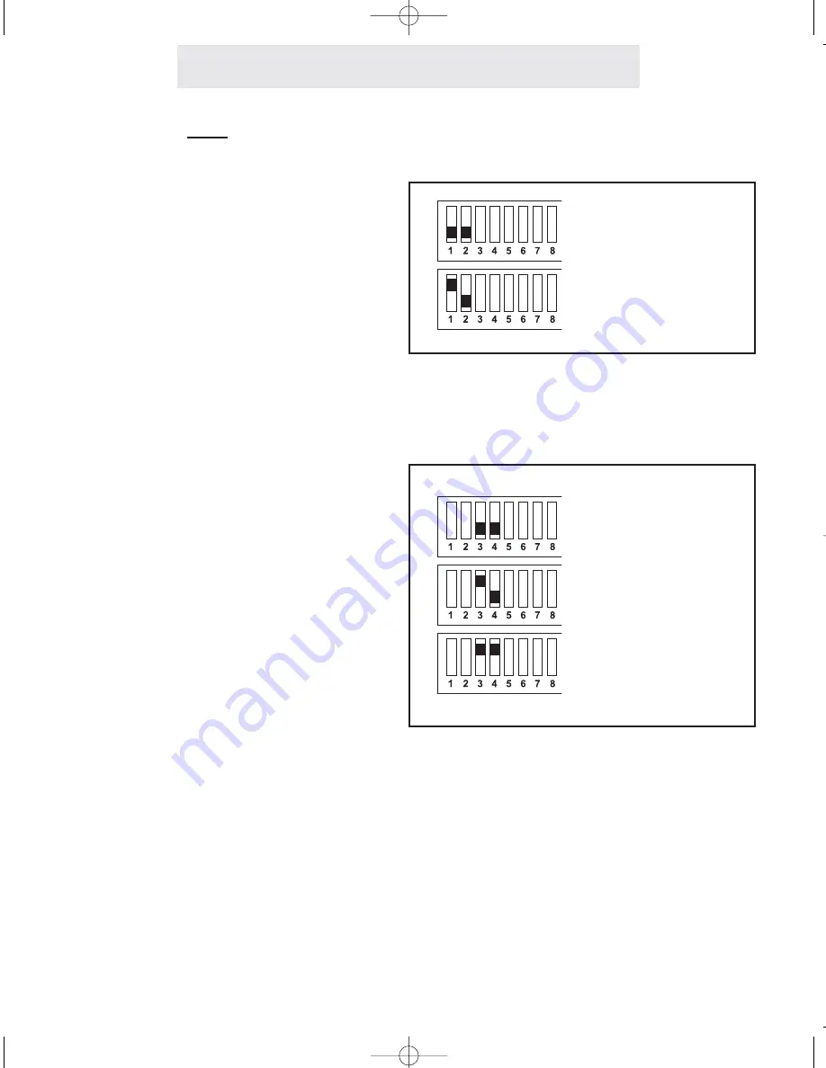
Step 3: Set Left DIP Switches to Proper Positions
Set Switches 1-2
The setting of these two DIP switches
determines the ringer setting for line 1.
Please refer to the drawing at the right to
determine how to set the DIP switches for
line 1.
Set Switches 3-8
The setting of these six DIP switches
determines the line and ringer settings for
lines 2, 3, and 4.
Please refer to the drawing at right for
instructions on setting each line. Note that
the drawing illustrates setting DIP switch-
es 3-4 for setting line 2. Set DIP switches
5-6 in the same manner to set line 3, and
set DIP switches 7-8 in the same manner
to set line 4.
Ringer ON
Ringer OFF
Ringer ON
Ringer OFF
Line
UNCONNECTED
4
ECA for PDF v13 070903.qxd 7/9/2003 3:30 PM Page 11


