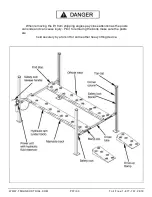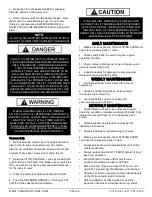
Fig 3.2
STEP 3
(Column & Crosstube Installation)
1.
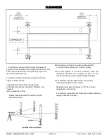
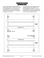
Place a chalk line on the floor according to the floor
plan layout. Pay attention to the power Unit location.
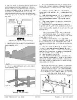
Locate and stand the columns at their respective locations.
DO NOT BOLT Columns down at this time. Use caution to
prevent the Columns from falling over. (See Fig. 3.1)
Fig 3.1
(If not bolting lift to the floor, skip to Item 3.)
2.
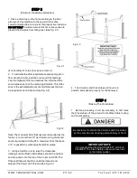
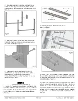
To estimate the shim requirements, place a target on
floor at each Column position and record the readings.
Find the highest of the four locations then find the differ-
ence between each of the remaining Columns. This differ-
ence is the estimated amount of shim thickness that will
be required at each Column. (See Fig. 3.2)
Note: The maximum shim thickness recommended by the
factory is no more than 1/2” per Column using shims and
anchors provided with the lift. A maximum shim thickness
of 2” is possible by ordering optional shim plates.
3.
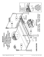
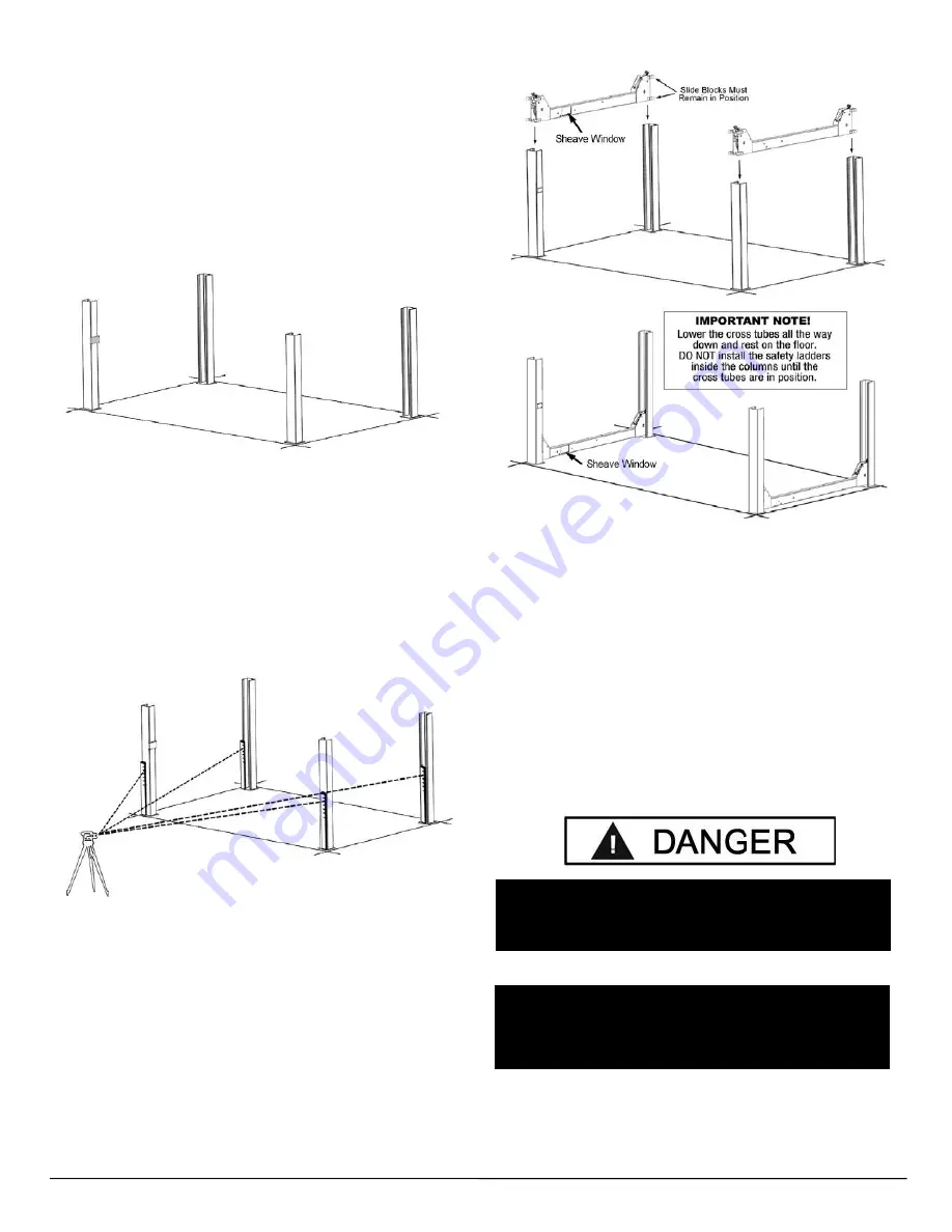
Using a forklift or crane, raise the crosstubes
(making sure the Plastic Slide Blocks are still in position)
and drop down into the top of the Columns. NOTE: The
Sheave Windows should be positioned inward and
adjacent the Power Unit Column. (See Fig. 3.3)
4.
The Columns and Crosstubes will now be in
position and spaced properly for the Runways.
STEP 4
(Raising The Crosstubes)
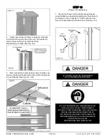
1.
Before proceeding it will be necessary to first raise
the Crosstubes off the ground to facilitate Cable routing
and final assembly.
Fig 3.3
IMPORTANT NOTE
It is important that the SLACK SAFETY LOCK IS
CLEARED. The Slack Safety Lock must never rest
on the Safety Ladder.
Be careful not to disturb the Columns and Crosstubes
as they may tip over causing personal injury or harm
WWW.TMGINDUSTRIAL.COM
P11/33
Toll Free:1-877-761-2819

