6.
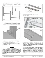
After any necessary shims are installed, tighten each
nut 3-5 turns past hand tight. IMPORTANT - If anchor
bolts do not hold when tightened to indicated amount,
concrete must replaced. Saw cut and remove 24” x 24”
square area each column base then re-pour with
reinforced 2500 PSI concrete to a depth of six inches
minimum, keying new concrete under existing floor. (See
Fig. 14.5)
STEP 15
(Attaching the Approach Ramp /Tire Stops)
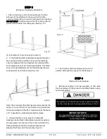
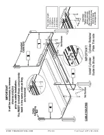
1.
Install the Front Tire Stops at the forward side of
the lift. (See Fig. 15.1)
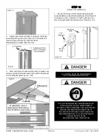
2.
Install the Approach Ramps on the entry side of
the lift. (See Fig. 15.2)
STEP 16
(Leveling / Synchronizing)
1. Using an engineer’s automatic Level (transit), locate
the Level, at a convenient location in the shop that allows
an unobstructed view of all four corners of the runways.
2.
Follow the Level manufacturer’s instructions for
proper setup of the Level. Be sure it is adjusted level in all
directions.
3.
Raise the lift approximately 30”- 40”. Thenlower the
lift until all primary safeties are engaged in each column
and the runways are completely resting on the primary
safeties.
4.
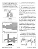
Place a Level target on the right/front corner of the
runway. (See Fig. 16.1)
5.
Beginning with “A” position, sight the level to the
target and mark the number or the graduation on the inch
scale of the target that aligns to the cross hairs of the Level.
(See Fig. 16.1)
Note:
Use a pencil, marking pen or attach a paper clip
onto the target scale at the cross hair reference.
6.
Next, move the target and place it at point “B” on the
runway. (See Fig. 16.1)
7.
Rotate the Level and focus on the target scale
8.
Adjust the adjustment nut on the safety ladder bar at
the top of the Column at “B” until the cross hairs of the
Level align to reference mark on the target scale. (See Fig.
15.1)
9.
Repeat steps locating the target assembly at points
“C” and “D” and adjusting Safety Ladders at each cor-
responding Column until the reference mark on the target
scale is on the cross hairs of the Level. The Runways are
now level at all four points. (See Fig. 16.1)
10. Next, load vehicle onto the lift.
11. Raise the lift to full height. Listen and watch as the
primary safeties engage the safety ladder. Synchronize by
adjusting the cables so that all four latches click at same
time. Make necessary adjustments to the cables allowing
compensation for stretch.
Safety locks may not engage at exactly the same time
when vehicles are being raised. They should be close.
Be sure that all four corners have passed the SAME
Safety Ladder position before lowering lift on the safety
locks. NEVER lower lift on different Safety Lock position
or damage to the lift may result.
Fig 14.5
Fig 15.2
Fig 15.1
Fig 16.1
WWW.TMGINDUSTRIAL.COM
P21/33
Toll Free:1-877-761-2819

