background image

VISUALLY CONFIRM THAT ALL PRIMARY SAFETY

LOCKS ARE ENGAGED BEFORE ENTERING WORK

AREA. SUSPENSION COMPONENTS USED ON

THIS LIFT ARE INTENDED TO RAISEAND

LOWER LIFT ONLY AND ARE NOT MEANT TO BE

LOAD HOLDING DEVICES. REMAIN CLEAR OF

ELEVATED LIFT UNLESS VISUAL CONFIRMATION

IS MADE THAT ALL PRIMARY SAFETY LOCKS ARE

FULLY ENGAGED AND THE LIFT IS LOWERED ONTO

THE SAFETY LOCKS, REFER TO INSTALLATION/

OPERATION MANUAL FOR PROPER SAFETY LOCK

PROCEDURES AND/OR FURTHER INSTRUCTION.

4.

Raise the lift to the desired height by pressing

the push button on the power unit.

5.

After vehicle is raised to the desired height, lower

the lift onto the nearest Safety Lock. Do not allow

Cables to become slack. ALWAYS ENSURE ALL

SAFETY LOCKS ARE ENGAGED before entering work

area.

To Lower Lift;

1.

Before lowering vehicle, be sure all personnel are

clear of the lift and surrounding area. Pay careful
attention to overhead clearances. Ensure all tools and
equipment have been cleared from under the lift.

2.

Raise the lift off of the Safety Locks by pressing the

push button on the Power Unit. Make sure you raise the

lift by at least two inches to allow adequate clearance

for the locks to clear.

3.

Press the safety lock release handle and HOLD.

4.

Push the LOWERING HANDLE on the Power Unit

until the lift has descended completely.

DAILY MAINTENANCE

1.

Make a visual inspection of ALL MOVING PARTS and

check for excessive signs of wear.

2.

Check safety locks to ensure they are in good

operating condition.

3.

Check cables and sheaves for wear. Replace worn

parts as required the parts.

4.

Inspect adapters for damage or excessive wear.

Replace as required with the parts.

WEEKLY MAINTENANCE

1.

Lubricate all Sheave and rollers with general

purpose oil.

2.

Check all Cable connections, bolts and pins

to ensure proper mounting.

3.

Lubricate Safety Lock pivot points with

general purpose oil or WD-40.

MONTHLY MAINTENANCE

1.

Check Safety Locks to ensure they are in good

operating condition. Lubricate locking latch shafts. Push

release arm several times for oil to penetrate pivot

points.

2.

Check equalizer cable tension. Adjust per lift

installation instructions.

3.

Check all Cables for excessive signs of wear.

4.

Make a visual inspection of ALL MOVING PARTS

and check for excessive signs of wear.

Always call local service representative if electrical

problems develop.

Always replace ALL FAULTY PARTS before lift is put

back into operation.

Every 3 Months: Check anchor bolt torque.

Anchors should be torqued to 90 ft/lbs.

Semi-Annually: Check fluid level of lift power unit

and refill if required per lift installation instructions.

Replace all caution, warning or safety related decals

on the lift if unable to read or missing.

Refer to ANSI/ALI ALOIM booklet for periodic

inspection checklist and maintenance log sheet.

NOTE:

ALLOW (2) SECONDS BETWEEN MOTOR STARTS.

FAILURE TO COMPLY MAY CAUSE MOTOR BURNOUT.

IF YOU ARE NOT COMPLETELY FAMILIAR WITH

AUTOMOTIVE LIFT MAINTENANCE PROCEDURES;

STOP AND CONTACT THE MANUFACTURER FOR

INSTRUCTIONS. TO AVOID PERSONAL INJURY,

PERMIT ONLYQUALIFIED PERSONNEL TO PERFORM

MAINTENANCE ON THIS EQUIPMENT.

WHEN LOWERING THE LIFT PAY CAREFUL

ATTENTION THAT ALL PERSONNEL AND OBJECTS

ARE KEPT CLEAR. ALWAYS KEEP A VISUAL LINE OF

SIGHT ON THE LIFT AT ALL TIMES. ALWAYS

MAKE SURE THAT ALL LOCKS ARE DISENGAGED.

IF ONE OF THE LOCKS INADVERTENTLY LOCKS

UPON DESCENT THE VEHICLE MAY DISMOUNT

CAUSING PERSONAL INJURY ORDEATH.

WWW.TMGINDUSTRIAL.COM

P23/33

Toll Free:1-877-761-2819

Summary of Contents for TMG-ALF90

Page 1: ...ompletely before assembly Check against the parts list to make sure all parts are received Wear proper safety goggles or other protective gears while in assembly Missing parts or questions on assembly...

Page 2: ...conforms to all applicable Local State and Federal Codes Rules and Regulations such as State and Federal OSHA Regulations and Electrical Codes Carefully check the lift for correct initial function Re...

Page 3: ...ubes 11 Step 5 PowersideRunway Installation 12 Step 6 OffsideRunway Installation 13 Step 7 Safety Lock Release Installation 13 Cable Routing 14 Step 8 Cable Sheave Installation 15 Step 9 Cable Install...

Page 4: ...o serious personal injury or death to operator or bystander or damage to property or lift Failure to follow danger warning and caution instructions may lead to serious personal injury or death to oper...

Page 5: ...ALWAYS ENSURE that the safeties are engaged before any attempt is made to work on or near vehicle 11 DRESS PROPERLY Non skid steel toe footwear is recommended when operating lift 12 GUARD AGAINST ELE...

Page 6: ...if covered and dry Always follow warnings illustrated on equipment labels STEP 2 Floor Requirements This lift must be installed on a solid level con crete floor with no more than 3 of slope Failure t...

Page 7: ...gles pay close attention as the posts can slide and can cause injury Prior to removing the bolts make sure the posts are held securely by a fork lift or some other heavy lifting device WWW TMGINDUSTRI...

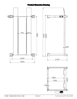
Page 8: ...ight of Columns 84 2 133 mm E Min Runway Height 4 1 2 115 mm F Max Rise 73 1 855mm G Max Lifting Height 77 1 955 mm H Width Between Columns 92 2 337mm I Runway Width 18 5 8 473 mm J Width Between Runw...

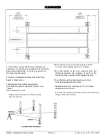
Page 9: ...rk locations where lift columns will be positioned in bay B Place target on floor at column positions NOT on column base plates and record readings C Find the highest of the four locations Find the di...

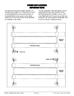
Page 10: ...er unit location Utility rails on the side of each Runway MUST be installed to the inside For the remainder of this instruction we will illustrate the Power Unit mounted at the DRIVER SIDE LEFT FRONTC...

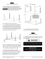
Page 11: ...is no more than 1 2 per Column using shims and anchors provided with the lift A maximum shim thickness of 2 is possible by ordering optional shim plates 3 Using a forklift or crane raise the crosstub...

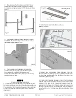
Page 12: ...he underside The Powerside Runway will be positioned on the side of the lift where the power unit is installed See Fig 5 1 2 Install Cylinder and Cable Block as shown See Fig 5 2 5 3 3 Remove any pre...

Page 13: ...r on the Crosstubes and install joint bearings with M6x25 Install long short unlock rod with M6X35 See Fig7 2 3 Connect the unlock handle and long unlock lever with the connecting sleeve See Fig7 3 4...

Page 14: ...WWW TMGINDUSTRIAL COM P14 33 Toll Free 1 877 761 2819...

Page 15: ...vere personal injury or death See page 11 STEP 9 Cable Installation 1 The Cylinder Flange Plate MUST be installed with the Guide Assembly facing down the welded on Spacer towards the Cylinder and the...

Page 16: ...s are made See Fig 9 4 Fig 9 4 5 After routing the Cables double check to make sure all are properly positioned and remain within thegrooves of ALL Sheaves See Fig 9 5 9 6 Fig 9 6 ALL WIRING MUST BE P...

Page 17: ...n on 50HZ without a physical change in motor Use a separate breaker for each Power Unit Protect each circuit with time delay fuse or circuit breaker For 208 230 volt single phase use a 25 amp fuse STE...

Page 18: ...IAN ONLY SEE WIRING INSTRUCTIONS AFFIXED TO MOTOR FOR PROPER WIRING INSTRUCTIONS IMPORTANT POWER UNIT INSTALLATION NOTES DO NOTrunpowerunitwithnooil Damageto pumpcanoccur Thepowerunitmustbe keptdry Da...

Page 19: ...nsmission fluid 2 Spray the inside of the Columns where the Slide Blocks glide with a light lubricant or WD 40 3 Test the Power Unit by pressing the push button switch If the motor sounds like it is o...

Page 20: ...and Validation ANSI ALI ALCTV 2011 Lift buyers are responsible for any special regional structural and or seismic anchoring requirements specified by any other agencies and or codes such as the Unifor...

Page 21: ...on the inch scale of the target that aligns to the cross hairs of the Level See Fig 16 1 Note Use a pencil marking pen or attach a paper clip onto the target scale at the cross hair reference 6 Next...

Page 22: ...ea while lift is in use DO NOT permit anyone on lift or inside vehicle when it is either being raised or lowered ALWAYS keep area around lift free of tools debris grease and oil NEVER overload lift Ca...

Page 23: ...ith the parts WEEKLY MAINTENANCE 1 Lubricate all Sheave and rollers with general purpose oil 2 Check all Cable connections bolts and pins to ensure proper mounting 3 Lubricate Safety Lock pivot points...

Page 24: ...ed by any method including pump spray dispensing brush hand and or swabbing HOW OFTEN TO INSPECT Lifting cables should be visually inspected at least once each day when in use as suggested by American...

Page 25: ...recommendations should be used for spotting and lifting the vehicle LIFT OPERATION SAFETY It is important that you know the load limit Be careful that you do not overload the lift If you are unsure w...

Page 26: ...t KEEP HANDS AND FEET CLEAR Remove hands and feet from any moving parts Keep feet clear of lift when lowering Avoid pinch points ONLY TRAINED OPERATORS should operate this lift All non trained personn...

Page 27: ...ing possible contamination it to run for 15 seconds 4 Dirty oil Replace oil with clean Dexron ATF 5 Tighten all fasteners Tighten fasteners to recommended torques 6 Check for free movement of release...

Page 28: ...w part 5 Reset circuit breaker fuse Reset circuit breaker fuse 6 Return unit for repair Return unit for repair 7 See Installation Manual See Installation Manual 8 Check wall outlet voltage and wiring...

Page 29: ...t Lift Manufacturer 6 Check vehicle weight Compare weight of vehicle to weight limit of the lift 7 Flush release valve Hold release handle down and start unit allowing it to run for 15 seconds 8 Repla...

Page 30: ...eal damaged and cocked Replace oil seal around pump shaft 3 Bleed cylinder Refer to Installation Manual 4 Flush release valve Hold release handle down and start unit allowing it to run for 15 seconds...

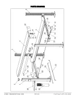
Page 31: ...PARTS DRAWING WWW TMGINDUSTRIAL COM P31 33 Toll Free 1 877 761 2819...

Page 32: ...g 8 28 Long Unlocking Lever 1 10 Fixing Sleeve 16 29 Short Unlocking Rod 2 11 Locking Block 4 30 Long unlocking rod 2 12 Locking Shaft 4 31 Handle Ball 1 13 Slider 8 32 Power Unit 1 14 Wire Rope Axle...

Page 33: ...Product Dimension Drawing WWW TMGINDUSTRIAL COM P33 33 Toll Free 1 877 761 2819...

Reviews: