W W W . T M G I N D U S T R I A L . C O M
P 0 5 / 4 1
T o l l F r e e : 1 - 8 7 7 - 7 6 1 - 2 8 1 9
INTRODUCTION
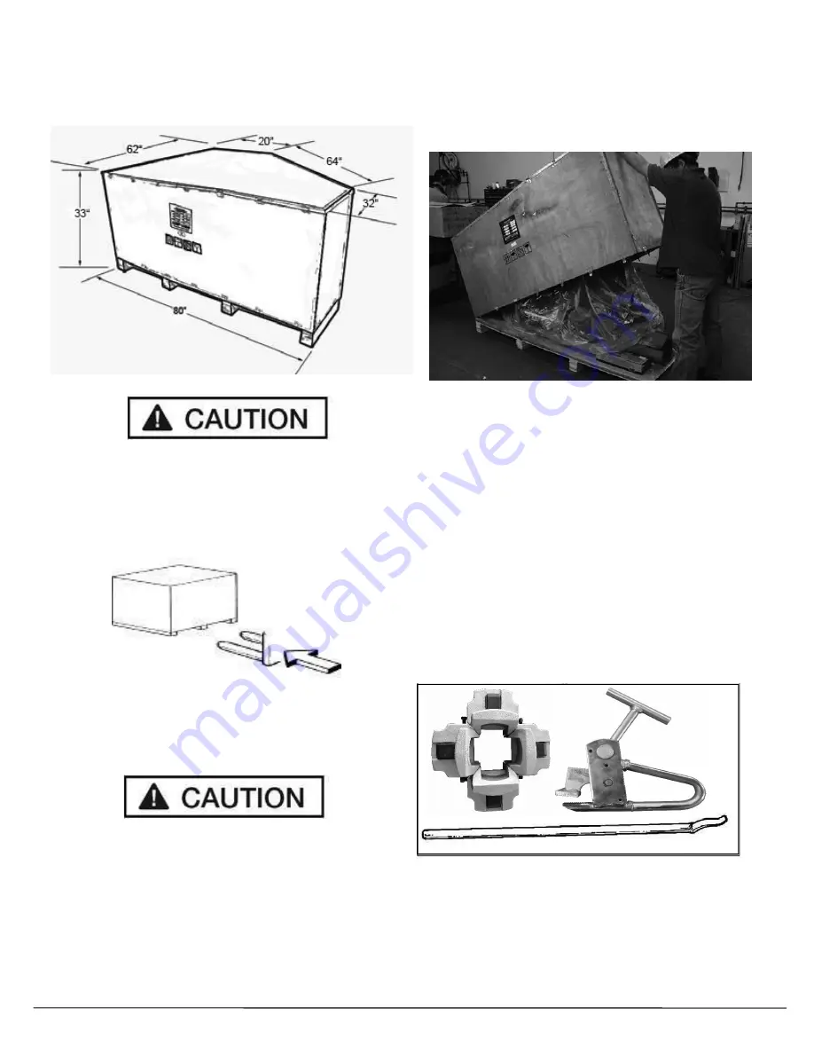
This tire changer is shipped on a pallet. Approximate
shipping dimensions are shown below.
Handling of the machine must be performed only with
an appropriate lifting device such as a forklift or pallet
jack. Only personnel who are experienced and quali-
fied on material handling procedures should handle
any transportation or moving of machine.
UNCRATING INSTRUCTIONS
Be careful when cutting steel/plastic banding material as
items may become loose and fall causing personal harm or
injury. Always wear gloves when uncrating the machine to
prevent scratches, abrasions, or cuts due to the contact
with packing materials. Eye protection is essential during
uncrating service activity. Safety glasses with side shields,
goggles, or face shields are acceptable.
Remember to report any shipping damage to the carrier
and make a notation on the delivery receipt.
Using a crow bar or pry bar, locate the staple/nail/tab
locations and pry off the bottom part the box.
NOTE:
The entire box can be lifted off after prying the
staples/nails/tabs at the base of the carton.
Remove the Control Pod, Sliding Carriage. Grease
Gun and Tire Irons from the pallet and set aside.
NOTE:
The Control pod is connect to the
Power Control Box via a cable.
NOTE:
The Sliding Carriage should be attached
after the Tire Changer is in the proper
operating location and wired correctly.
Open the Tool Storage Box, remove and inventory the
Accessories


