background image

Summary of Contents for 15560

Page 1: ...I N I TOOLS n TASKS TM MC 26 GALLON OIL FREE AiR COMPRESSOR Model 15560 S 218549 TOLL FREE HELPLINE 1 888 266 7096 FOR SAFE OPERATION READ AND UNDERSTAND ALL CONTENTS OF THE iNSTRUCTiON MANUAL ...

Page 2: ...s the safety alert symbol it is used to alert you to potential personal injury hazards Obey all safety messages that follow this symbol to avoid possible injury or death DANGER indicates a hazardous situation which if not avoided will result in death or serious injury WARNING indicates a hazardous situation which if not avoided could result in death or serious injury CAUTION used with the safety a...

Page 3: ...surfaces such as pipes radiators ranges and refrigerators There is an increased risk of electric shock if your body is earthed or grounded c Do not expose power tools to rain or wet conditions Water entering a power tool will increase the risk of electric shock d Do not abuse the cord Never use the cord for carrying pulling or unplugging the power tool Keep cord away from heat oil sharp edges or m...

Page 4: ...res reduce the risk of starting the power tool accidentally Store idle power tools out of the reach of children and do not allow people unfamiliar with the power tool or these instructions to operate the power tool Power tools are dangerous in the hands of untrained users Maintain power tools Check for misalignment or binding of moving parts breakage of parts and any other condition that may affec...

Page 5: ...m rupture or explosion Always replace worn cracked or damaged Tanks WARNING Never use plastic PVC pipe for compressed air serious injury or death could result Any tube pipe or hose used must have a pressure rating higher than 155 PSI Minimum recommended pipe size Up to 50 feet long use 1 2 diameter Greater than 50 feet use 3 4 diameter Larger diameter pipe is always better CAUTION DO NOT use an ex...

Page 6: ...ions discussed in this manual cannot cover all possible conditions and situations that may occur It must be understood by the operator that common sense and caution are factors which cannot be built into this product but must be supplied by the operator GROUNDING iNSTRUCTIONS This product must be grounded In the event of a malfunction or breakdown grounding provides a path of least resistance for ...

Page 7: ...t is properly grounded Repair or replace a damaged or worn cord immediately This product is for use on a nominal t20 V circuit and has a grounding plug similar to the plug illustrated in figure Only connect the product to an outlet having the same configuration as the plug Do not use an adapter with this product Plug Grounding pin Grounded Outlets 3 Prong Plug and Outlet Page 7 ...

Page 8: ...hen unpacking check to make sure that the item is intact and undamaged If any parts are missing or broken please call TOLL FREE HELPLINE at the number shown on the cover of this manual as soon as possible SET UP iNSTRUCTIONS Read the ENTIRE IMPORTANT SAFETY INFORMATION section at the beginning of this manual including all text under subheadings therein before set up or use of this product Risk of ...

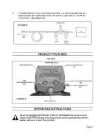
Page 9: ...Tool _ _ _ 1 _Y _ I I OILER WATER FILTER AIR COMPRESSOR SAFETY VALVE 18 PRODUCT FEATURES TOP VIEW POWER SWITCH 2 PROTECTOR 3 TANK AIR PRESSURE 120 PRESSURE GAUGE 19 QUICK CONNECTOR 24 FIGURE B REGULATOR 17 OPERATING INSTRUCTIONS Read the ENTIRE IMPORTANT SAFETY INFORMATION section at the beginning of this manual including all text under subheadings therein before set up or use of this product Page...

Page 10: ...Turn the Power Switch 2 to its ON position to start the unit See Figure B When the Tank Air Pressure Gauge 20 reaches at least 125 PSI turn the air Regulator 17 clockwise or counterclockwise to allow the proper amount of air flow to reach the pneumatic tool being used See Figure B NOTE The Regulator adjusts as follows Clockwise to increase tool air pressure Counterclockwise to decrease tool air pr...

Page 11: ...ition and unplug the tool from its electrical outlet before performing any inspection maintenance or cleaning procedures Damaged equipment can fail causing serious personal injury Do not use damaged equipment if abnormal noise or vibration occurs have the problem corrected before further use Ins ection Maintenance And Cleanin BEFORE EACH USE inspect the general condition of the Air Compressor Chec...

Page 12: ... pneumatic tool 1 Immediately disconnect Power Cord from its electrical outlet Do not use Compressor until a qualified service technician repairs Power Switch PLEASE READ THE FOLLOWING CAREFULLY THE MANUFACTURER AND OR DISTRIBUTOR HAS PROVIDED THE PARTS LIST AND ASSEMBLY DIAGRAM IN THIS MANUAL AS A REFERENCE TOOL ONLY NEITHER THE MANUFACTURER OR DISTRIBUTOR MAKES ANY REPRESENTATION OR WARRANTY OF ...

Page 13: ...ket Support 3 14 3410283 Cover Bottom 1 15 3220106 Screw 2 16 3640183 Power Cord 1 17 31103119 Regulator turncap 1 18 3390853 Safety Valve 1 Part No Description Q ty 19 3290283 1 Output Air Pressure Gauge 1 20 3290183 1 Tank Air Pressure Gauge 1 21 3411535 Wire clip 1 22 3330283 Handle 1 23 3110283 1 Pressure Valve 1 24 3321175 Quick Connector 1 25 3110282 1 Screw 4 26 3390183 8 Tu be 1 27 3330119...

Page 14: ...ASSEMBLY DIAGRAM I 4 3 2 5 24 34 19 18 20 1723 22 25 15 21 16 I iI Page 14 ...

Page 15: ...m defects in material and workmanship for a period of one hundred twenty 120 days from the date of retail purchase How to Obtain Service Warranty service is available by calling the toll free helpline at 1 888 266 7096 The factory will not accept the return of a complete unit unless prior written permission has been extended by SEARS Transportation Charges Transportation charges for the movement o...

Page 16: ...I N I TOOLS n TASKS TM MC 26 GALLON OIL FREE AiR COMPRESSOR Model 15560 S 218549 TOLL FREE HELPLINE 1 888 266 7096 FOR SAFE OPERATION READ AND UNDERSTAND ALL CONTENTS OF THE iNSTRUCTiON MANUAL ...

Page 17: ...s the safety alert symbol it is used to alert you to potential personal injury hazards Obey all safety messages that follow this symbol to avoid possible injury or death DANGER indicates a hazardous situation which if not avoided will result in death or serious injury WARNING indicates a hazardous situation which if not avoided could result in death or serious injury CAUTION used with the safety a...

Page 18: ...surfaces such as pipes radiators ranges and refrigerators There is an increased risk of electric shock if your body is earthed or grounded c Do not expose power tools to rain or wet conditions Water entering a power tool will increase the risk of electric shock d Do not abuse the cord Never use the cord for carrying pulling or unplugging the power tool Keep cord away from heat oil sharp edges or m...

Page 19: ...res reduce the risk of starting the power tool accidentally Store idle power tools out of the reach of children and do not allow people unfamiliar with the power tool or these instructions to operate the power tool Power tools are dangerous in the hands of untrained users Maintain power tools Check for misalignment or binding of moving parts breakage of parts and any other condition that may affec...

Page 20: ...m rupture or explosion Always replace worn cracked or damaged Tanks WARNING Never use plastic PVC pipe for compressed air serious injury or death could result Any tube pipe or hose used must have a pressure rating higher than 155 PSI Minimum recommended pipe size Up to 50 feet long use 1 2 diameter Greater than 50 feet use 3 4 diameter Larger diameter pipe is always better CAUTION DO NOT use an ex...

Page 21: ...ions discussed in this manual cannot cover all possible conditions and situations that may occur It must be understood by the operator that common sense and caution are factors which cannot be built into this product but must be supplied by the operator GROUNDING iNSTRUCTIONS This product must be grounded In the event of a malfunction or breakdown grounding provides a path of least resistance for ...

Page 22: ...t is properly grounded Repair or replace a damaged or worn cord immediately This product is for use on a nominal t20 V circuit and has a grounding plug similar to the plug illustrated in figure Only connect the product to an outlet having the same configuration as the plug Do not use an adapter with this product Plug Grounding pin Grounded Outlets 3 Prong Plug and Outlet Page 7 ...

Page 23: ...hen unpacking check to make sure that the item is intact and undamaged If any parts are missing or broken please call TOLL FREE HELPLINE at the number shown on the cover of this manual as soon as possible SET UP iNSTRUCTIONS Read the ENTIRE IMPORTANT SAFETY INFORMATION section at the beginning of this manual including all text under subheadings therein before set up or use of this product Risk of ...

Page 24: ...Tool _ _ _ 1 _Y _ I I OILER WATER FILTER AIR COMPRESSOR SAFETY VALVE 18 PRODUCT FEATURES TOP VIEW POWER SWITCH 2 PROTECTOR 3 TANK AIR PRESSURE 120 PRESSURE GAUGE 19 QUICK CONNECTOR 24 FIGURE B REGULATOR 17 OPERATING INSTRUCTIONS Read the ENTIRE IMPORTANT SAFETY INFORMATION section at the beginning of this manual including all text under subheadings therein before set up or use of this product Page...

Page 25: ...Turn the Power Switch 2 to its ON position to start the unit See Figure B When the Tank Air Pressure Gauge 20 reaches at least 125 PSI turn the air Regulator 17 clockwise or counterclockwise to allow the proper amount of air flow to reach the pneumatic tool being used See Figure B NOTE The Regulator adjusts as follows Clockwise to increase tool air pressure Counterclockwise to decrease tool air pr...

Page 26: ...ition and unplug the tool from its electrical outlet before performing any inspection maintenance or cleaning procedures Damaged equipment can fail causing serious personal injury Do not use damaged equipment if abnormal noise or vibration occurs have the problem corrected before further use Ins ection Maintenance And Cleanin BEFORE EACH USE inspect the general condition of the Air Compressor Chec...

Page 27: ... pneumatic tool 1 Immediately disconnect Power Cord from its electrical outlet Do not use Compressor until a qualified service technician repairs Power Switch PLEASE READ THE FOLLOWING CAREFULLY THE MANUFACTURER AND OR DISTRIBUTOR HAS PROVIDED THE PARTS LIST AND ASSEMBLY DIAGRAM IN THIS MANUAL AS A REFERENCE TOOL ONLY NEITHER THE MANUFACTURER OR DISTRIBUTOR MAKES ANY REPRESENTATION OR WARRANTY OF ...

Page 28: ...ket Support 3 14 3410283 Cover Bottom 1 15 3220106 Screw 2 16 3640183 Power Cord 1 17 31103119 Regulator turncap 1 18 3390853 Safety Valve 1 Part No Description Q ty 19 3290283 1 Output Air Pressure Gauge 1 20 3290183 1 Tank Air Pressure Gauge 1 21 3411535 Wire clip 1 22 3330283 Handle 1 23 3110283 1 Pressure Valve 1 24 3321175 Quick Connector 1 25 3110282 1 Screw 4 26 3390183 8 Tu be 1 27 3330119...

Page 29: ...ASSEMBLY DIAGRAM I 4 3 2 5 24 34 19 18 20 1723 22 25 15 21 16 I iI Page 14 ...

Page 30: ...m defects in material and workmanship for a period of one hundred twenty 120 days from the date of retail purchase How to Obtain Service Warranty service is available by calling the toll free helpline at 1 888 266 7096 The factory will not accept the return of a complete unit unless prior written permission has been extended by SEARS Transportation Charges Transportation charges for the movement o...

Reviews: