background image

Specifications

Type

Rated Output

Power Band Width

Frequency Response

Total Hamonic Distortion

Inputs

Input Sensitivity/Impedance

Outputs

Output Regulation (1 kHz)

Signal to Noise Ratio

(Band Pass 20 ~20,000 Hz)

Tone Controls Centered

Tone Contols

Controls

Indicators

Protection

Connectors

Power Consumption

Temperature  Range

Dimensions  (W)  x  (H)  x  (D)

Weight

Color

Standard Accessories

Other Features

8-channel  mixer preamplifier

+4 dBm, +20 dBm  (max.)

30 ~20,000 Hz, +20 dBm 0.5% THD
25 ~20,000 Hz, +18 dBm 0.5% THD

20 ~20,000 Hz, ± 1 dB

0.01% at 1  kHz, rated output

Eight Input Ports : Each port accepts any input module.

One Bridging  Input/Output

Input Port #1  to #8 : 100 mV/10k ohms
Bridging  Input/Output :100  mV/3.3k ohms

Main : Balanced, 150/600 ohms

Aux : Unbalanced, 10k ohms,  0  dBm

Less than 1 .5 dB, no load to full load

Master volume min : 90 dB

Master volume max : 77 dB

Bass:  ± 10 dB at 100 Hz, Treble :  ± 10 dB at 10 kHz

8 Input gain controls 

1  Master gain control

1  Bass tone control 

1  Treble control

1  Power ON/OFF switch 

1  Tone defeat switch

1  Power LED, 1  Protect LED, 1  Signal LED, 1  Normal LED,

1  Peak LED

Self-protection, with AC fuse (inside)

Input No.1 to No. 8 ..................  Card-edge connector

Bridging, Aux output ...............  RCA phono jack

Output .....................................  Screw-terminal strip

Mute, Remote VR ................... Screw-terminal strip

AC power cord/plug ................ SJT, 3-prong type
AC outlet .................................  3-pin grounding type

18W

- 1 0 ° C ~ + 6 0 ° C ( 1 2 ° F ~ 1 4 0 ° F )

420 x 99.1  x 307.5 mm (16.5 x 3.9 x  12.1  in.)

5.3  kg(11.7lb.)

Black

4 Volume control covers (YA-920)

Output disconnected for approx. 5 seconds after switching power on.

Specifications are subject to change without notice.

— 9 —

All manuals and user guides at all-guides.com

Summary of Contents for 900 II Series

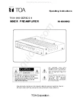
Page 1: ...THE USER THAT IMPORTANT OPERATING AND SERVICING INSTRUCTIONS ARE IN THE PAPERS WITH THE APPLIANCE Please follow the instructions in this manual to obtain the optimum results from this unit We also recommend that you keep this manual handy for future reference TOA Corporation TO REDUCE THE RISK OF ELECTRICAL SHOCK DO NOT REMOVE COVER NO USER SERVICEABLE PARTS INSIDE REFER SERVICING TO QUALIFIED SER...

Page 2: ... Input connections Output connections Muting and remote volume control connection Rack mounting Operation Volume adjustment Tone control adjustment Installation Servicing Specifications Appearance 3 3 4 5 6 6 7 7 8 8 8 8 8 9 10 2 All manuals and user guides at all guides com ...

Page 3: ...ut for operation with 600 ohms or 150 ohms loads Other features include a tone defeat switch muting functions remote master volume control and connections for another mixer preamplifier or mixer power amplifiers A 903MK2 A 906MK2 and A 912MK2 Features 1 8 channel mixer preamplifier 2 Wide frequency response 20 20 000 Hz 1 dB 3 Low distortion and noise level 4 Parallel operation of two mixer preamp...

Page 4: ...l the LED flashes only intermittently Protection Indicator LED Remains lit for about 5 seconds after power switch is turned ON Input Volume Controls Adjust gain of input 1 8 respectively Bass Control Modifies bass response Turn clockwise to boost counter clockwise to attenuate the bass response Tone is flat at center Treble Control Modifies treble response Turn clockwise to boost counter clockwise...

Page 5: ... This terminal is used as a mixing bus Mixing is achieved when the similar terminal of another amplifier is connected to this terminal The output level taken from this terminal is independent of Master Volume Control Bass and Treble Controls so that the terminal can also be used as recording output The input impedances of the equipment to be connected here should be of more than 10k ohms Remote Vo...

Page 6: ...fier s to the output terminal of M 900MK2 Select 600 ohm or 150 ohm connection provided at the output terminal to match the input impedance of amplifier s 600 ohm connection 150 ohm connection AUX Out For this connection use RCA phone jack with shielded cable Hot Earth External equipment such as tape recorder etc Cover unoccupied INPUT PORTS with blank panels Secure blank panels with screws Hot Co...

Page 7: ... use the optional MB 25B rack mounting bracket MB 25B Remove 4 screws securing case Fix the brackets with attached 4 screws The length of screws should not exceed 12mm 1 2 Amplifier PF 511 perforated panel 1 unit size If two or more units are mounted in an equipment rack provide space for ventilation The perforated panel PF 511 optional is recommended for this purpose 7 All manuals and user guides...

Page 8: ...n tone controls are unnecessary set the tone switch to ON mode Installation Never block ventilation holes The amplifier should never be placed in areas exposed to direct sunlight with high humidity or dust levels with high ambient temperatures susceptible to vibration with poor ventilation adjacent to heat generating equipment CAUTION Do not remove the case or you may encounter an electric shock S...

Page 9: ...lanced 150 600 ohms Aux Unbalanced 10k ohms 0 dBm Less than 1 5 dB no load to full load Master volume min 90 dB Master volume max 77 dB Bass 10 dB at 100 Hz Treble 10 dB at 10 kHz 8 Input gain controls 1 Master gain control 1 Bass tone control 1 Treble control 1 Power ON OFF switch 1 Tone defeat switch 1 Power LED 1 Protect LED 1 Signal LED 1 Normal LED 1 Peak LED Self protection with AC fuse insi...

Page 10: ...Appearance Front View Rear View Top View Side View 10 All manuals and user guides at all guides com ...

Page 11: ...TOA Corporation KOBE JAPAN PRINTED IN TAIWAN 133 12 115 50 All manuals and user guides at all guides com a l l g u i d e s c o m ...

Reviews: