11
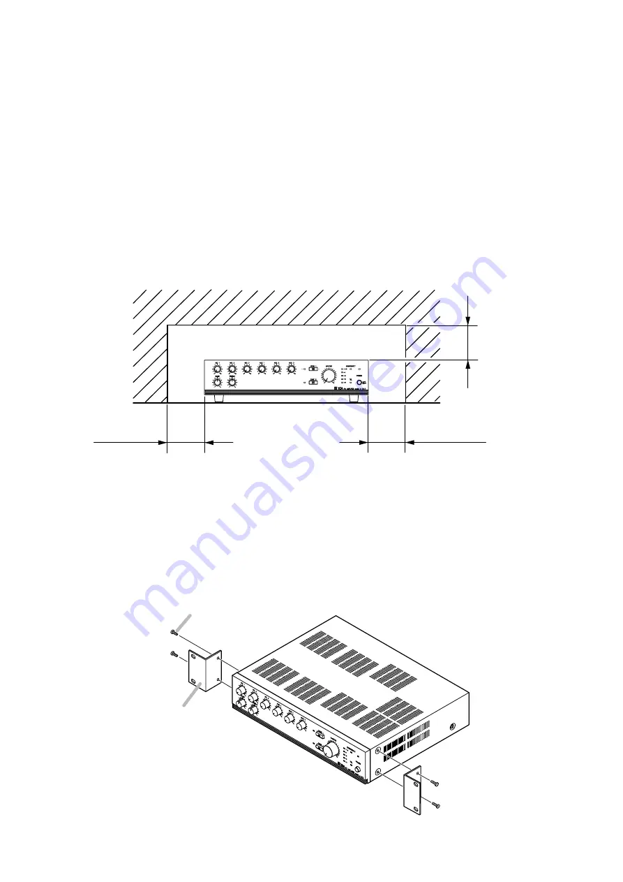
Over 10 cm
Over 10 cm
Over 10 cm
9. SPEAKER ZONE SELECTION
Pressing the front-mounted ZONE 1 switch permits its zone indicator to light and makes broadcast through the
speakers connected to the rear-mounted Zone 1 output terminals.
Operation for ZONE 2 is performed in the same way as above.
Shorting the Emergency Control or Telephone Paging Control input terminals turns on both Zone 1 and 2
switches (their indicators light), even if off, allowing the Emergency or Telephone Paging input signals to be
broadcast from both ZONE 1 and 2 speaker outputs.
Opening the control input terminals automatically returns the operation to the original status.
10. INSTALLATION
Keep the unit's all sides over 10 cm away from objects that may obstruct air flow to prevent the unit's internal
temperature rise.
11. RACK MOUNTING
To mount the unit in a standard 19" equipment rack, use the optional MB-25B Rack Mounting Bracket.
Attach the MB-25B to the unit using the supplied 4 screws. When using other screws, each screw must be
shorter than 16 mm.
MB-25B
M4 x 16 Machine screw
included in MB-25B


