22
7. CONNECTION EXAMPLE
7.1. System Example
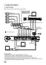
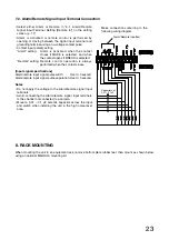
Make connections referring to the following connection diagram.
Wiring Precautions
• Connect the power cable after completing all equipment connections.
• Ensure that the unit's power is switched OFF before connecting the power cable.
• Do not apply the voltage to the unit's individual video inputs and output terminals.
• When black-and-white cameras are connected, monitor displays may become slightly colored.
• When line-locked cameras are connected, video images may be distorted. In such cases, switch the camera
synchronization system to internal synchronization mode.
Monitor TV
Monitor TV
Monitor TV
: BNC connector (optional)
Single-cable camera
C-QA40
C-QA40
Separate room
Camera Drive Unit
VIDEO IN
VIDEO IN
VIDEO IN
VCR
IN
IN
IN
IN
OUT
OUT
OUT
OUT
CAMERA OUT
CAMERA OUT
CAMERA OUT
CAMERA OUT
GND
Alarm input
Camera 1
Camera 2
Camera 3
Camera 4
Tab
Input 1
Input 2
Input 3
Input 4
Monitor 1
Input 1
Input 2
Input 3
Input 4
Output 1
Output 2
Output 3
Output 4
Monitor 1
Monitor 2
Alarm output
(For connection,
refer to p. 23.)
Insert a cable
pushing in the tab
with a screwdriver
blade.
GND


