23
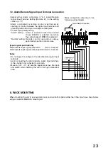
7.2. Alarm/Remote Signal Input Terminal Connection
Capacitors of
0.01– 0.1
µ
F
Alarm/Remote inputted
Make connections referring to the
following wiring diagram.
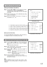
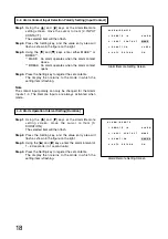
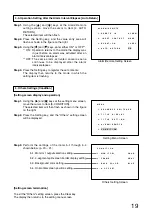
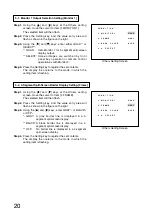
• Select either Alarm or Remote in "4-1. Alarm/Remote
Signal Input Terminal Setting [Remote In]" on the setting
screen. (p. 17)
• Alarm is activated or remote control is performed by
opening or closing between the signal input terminal and
grounding terminal using a no-voltage contact pulse.
• Contact input polarity setting
"Alarm" setting:
Alarm is activated when the contact
closes if MAKE is selected, and when
the contact opens if BREAK is selected.
"Remote" setting: Remote control operation is always
performed when the contact closes.
[Input signal specifications]
Alarm/remote input signal pulse width:
Over 0.3 second
Alarm/remote input signal pulse separation: Over 0.3 second
Notes
• Do not apply the voltage to the Alarm/remote signal input
terminals.
• Avoid connecting the Alarm/remote signal input terminals
to the channel not connected to a camera.
• Mount a 0.01 – 0.1 µF ceramic capacitor across the input
and switch when installing the unit in the high noise level
area.
8. RACK MOUNTING
When mounting the unit in an equipment rack, remove bottom plate rubber feet, then mount as shown below
using an optional MB-QA40 mounting kit.


