133-12-658-10
10. SPECIFICATIONS
Power Source
110 – 240 V AC, 50/60 Hz
Power Consumption
7 W
Camera Input
VBS 1.0 V(p-p), 75
Ω
, BNC, 4 channels (asynchronous, with Loop Through
output)
Video Output
VBS 1.0 V(p-p), 75
Ω
, BNC, 2 channels
Monitor 1: 4-segment split-screen display or display selected with Monitor 2
Monitor 2: Full-screen/4-segment split-screen display or sequential switching
(4-segment split-screen image: Real-time display)
External Control Input
Alarm/remote input signal pulse width: Over 0.3 second
and Output
Alarm input:
1, 2, 3, 4, alarm reset (shared with Remote Input)
Activation by no-voltage contact input to between alarm
signal input terminal and grounding terminal*
Remote input:
1, 2, 3, 4, sequential switching, QUAD mode
Activation by no-voltage contact input to between remote
signal input terminal and grounding terminal*
Remote operation: Remote control of individual front panel keys (edge type
last-in-first-out priority)
Alarm output:
Open collector output, 12 V DC, under 30 mA
Title Display
Up to 8 alphanumeric characters for each channel
Synchronizing System
Internal synchronization
Automatic Sequential
Automatic switching interval: 1 – 60 seconds, Skip function (selection for each
Switching input)
Operating Temperature
0 – 40°C
Operating Humidity
30 – 90% (no due condensation must be formed)
Range
Finish
Panel: ABS resin, black, paint
Case: Pre-coated steel plate, black
Dimensions
350 (w) x 44 (h) x 298 (d) mm (except protrusion)
Weight 2.5
kg
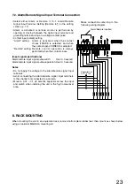
* Refer to p. 23 "Alarm/Remote Signal Input Terminal Connection."
Note:
The design and specifications are subject to change without notice for improvement.
• Accessory
Power cord (2 m) ........................................ 1
9. WHEN YOU THINK THERE IS A FAILURE
No image is displayed.
Symptom
Noise appears on screen image.
Neither remote input nor alarm input
operates correctly.
Cause
Power cable is not connected to AC wall outlet.
Power switch is not set to ON position.
No video signal input from camera.
Monitor output is not correctly connected to monitor.
Camera's coaxial cable is not correctly connected.
Power cable is installed in close proximity to camera's coaxial cable.
Signal remains applied to the input terminal.
Cable is not correctly connected.
Noise exists in cable.
Input detection polarity is not correctly set.
•
•
•
•
•
•
•
•
•
•


