5
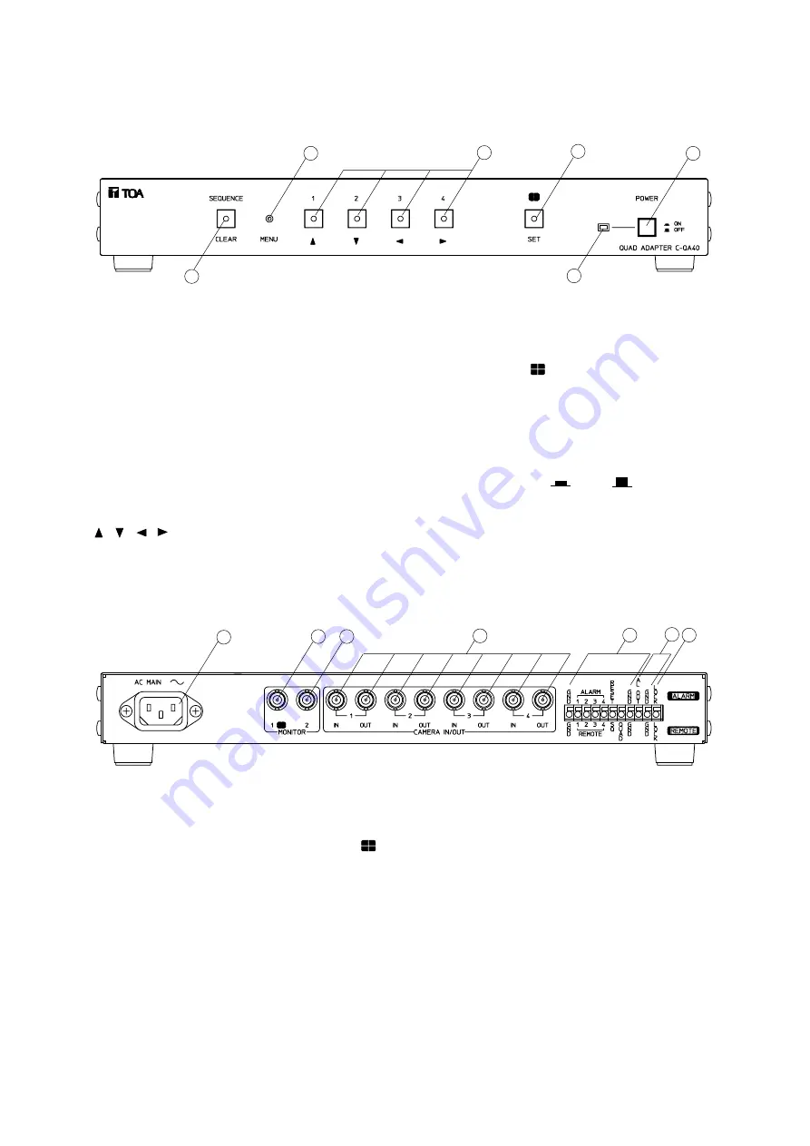
4. NOMENCLATURE AND FUNCTIONS
[Front]
1
2
3
4
5
6
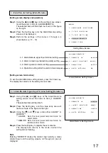
1. Sequence/Clear Key
Sequentially switches the outputs of cameras 1-4
at set time interval (p. 12) for monitor display
through the Monitor 2 output terminal.
Pressing this key (its lamp lights) while the setting
screen is displayed returns the screen to the
previous setting screen. (If pressed while the
setting menu screen is displayed, the setting
screen mode is terminated.) (p. 9)
2. Menu Key
Displays and terminates the setting screen.
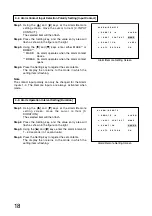
3. Channel Selector [1 – 4]/Cursor Control Keys
[
, , , ]
Pressing any one of these illuminated keys
transmits its corresponding channel image to the
Monitor 2 output terminal. When the setting screen
is displayed, these keys are also used to move the
cursor . (p. 9)
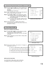
4. Quad Display [
]/Setting Key
Pressing this illuminated key transmits the quad
display video signal to the Monitor 2 output
terminal. This key is also used to select and
register the setting item when the setting screen is
displayed. (p. 9)
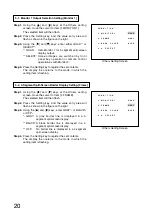
5. Power Switch [ON
/OFF
]
Press to switch ON or OFF power.
6. Power Lamp
Lights when the power is switched on.
[Rear]
7
8
9
10
11
12 13
7. AC Inlet
Insert the supplied power cable and connect to
the nearest available AC wall outlet.
8. Monitor 1 Output Terminal [MONITOR 1,
]
Used exclusively for 4-segment split screen
display. (75
Ω
termination)
Can be synchronized with Monitor 2 terminal by
changing the setting. (Refer to p. 20 "Monitor 1
Output Selection Setting.")
9. Monitor 2 Output Terminal
Used for video signals (spot output) selected with
the front panel keys. Connect this terminal to the
monitor's video input terminal. (75
Ω
termination)
10. Camera Video Input/Output Terminal
Connecting the camera video signal to this input
automatically terminates the internal impedance
at 75
Ω
. When the camera video output is
connected to external equipment, the output
termination is automatically released.
11. Alarm/Remote Signal Input Terminals
For alarm signal input, remote control signal
input and ground. (Refer to p. 23.)
12. Alarm Signal Output Terminal
Outputs alarm signals when alarm is activated.
This terminal is an open collector output (12 V DC
and less than 30 mA). (Refer to p. 22.)
13. Key Input Disable Terminal
Front panel key (1 – 4) operations can be
disabled by connecting this terminal to the GND
terminal.


