background image

6

5. BASIC OPERATIONS

Operating Precautions 

: Please read this manual carefully to avoid operation errors.

5.1. Switching on the Power 

• Ensure that all connections, especially those of the power cables, are

secure.

• Switch ON the power by pressing the front panel Power switch, and

check to confirm that the power lamp lights. When the power is first
switched on, the video signal for automatic sequential switching is
output to the Monitor 2 output terminal by default.

• When finished with use, switch off the power and check to ensure that

the power lamp is extinguished. 

Note

To prevent equipment failures and malfunction, do not remove or insert
the power cable when the power is on. 

5.2. Camera Image Selection (Monitor 2 Output Terminal)

• Press the Sequence key and confirm that its indicator lamp lights. The

Quad Adapter will then be placed in automatic sequential switching
mode.

• Press the desired Channel Selector key (1 – 4) to select the camera

image for output to the Monitor 2 output terminal.

Important

Check to be sure that the camera image of the selected channel is
displayed on the monitor. 

• Pressing the Quad Display key converts the camera images of

channels 1 – 4 into a 4-segment split-screen signal, and the signal is
output to the Monitor 2 output terminal.

Note

The Monitor 1 output terminal is factory-preset to continuously output 4-
segment split-screen images. If Monitor 1 is registered as [SYNCH] (Item
5-1. on p. 20), a desired image can be selected with the Sequence,
Channel Selector, or Quad Display keys. (Monitor 1 provides the same
operation as Monitor 2.)

Summary of Contents for C-QA40

Page 1: ...PERATING INSTRUCTIONS QUAD ADAPTER C QA40 Please follow the instructions in this manual to obtain the optimum results from this unit We also recommend that you keep this manual handy for future reference ...

Page 2: ...etting Sequence Skip 12 2 Title Display and Position Settings Title Display 13 2 1 Full screen Title Display Setting Full Screen 13 2 2 4 Segment Split Screen Title Display Setting Quad Screen 14 2 3 Title Display Position Setting Position 14 3 Title Setting Title Setting 15 4 Alarm Remote Setting Alarm Remote 17 4 1 Alarm Remote Signal Input Terminal Setting Remote In 17 4 2 Alarm Contact Input D...

Page 3: ... materials in the ventilation slots of the unit s cover as this may result in fire or electric shock Do not touch the power supply plug during thunder and lightning as this may result in electric shock When Installing the Unit Never plug in nor remove the power supply plug with wet hands as doing so may cause electric shock When unplugging the power supply cord be sure to grasp the power supply pl...

Page 4: ...ety purposes when cleaning or leaving the unit unused for 10 days or more A fire or electric shock may result 2 GENERAL DESCRIPTION TOA s C QA40 Quad Adapter reduces the video images of up to 4 connected asynchronous color or black and white B W cameras to quarter size and displays these images on a monitor as a 4 segment split screen display 3 FEATURES Up to four asynchronous cameras can be conne...

Page 5: ... Lamp Lights when the power is switched on Rear 7 8 9 10 11 12 13 7 AC Inlet Insert the supplied power cable and connect to the nearest available AC wall outlet 8 Monitor 1 Output Terminal MONITOR 1 Used exclusively for 4 segment split screen display 75 Ω termination Can be synchronized with Monitor 2 terminal by changing the setting Refer to p 20 Monitor 1 Output Selection Setting 9 Monitor 2 Out...

Page 6: ...2 Camera Image Selection Monitor 2 Output Terminal Press the Sequence key and confirm that its indicator lamp lights The Quad Adapter will then be placed in automatic sequential switching mode Press the desired Channel Selector key 1 4 to select the camera image for output to the Monitor 2 output terminal Important Check to be sure that the camera image of the selected channel is displayed on the ...

Page 7: ...larm Signal output terminal is grounded via a transistor Use the Alarm Remote output terminals on 12 V DC and under 30 mA When the alarm is simultaneously activated in several camera channels the alarm activated channel outputs are automatically sequenced to the monitor at one second intervals The alarm can be reset by pressing the Channel Selector key Sequence key or Quad Display key any key othe...

Page 8: ... set Monitor 2 screen images cannot be frozen when in full screen display mode F R E E Z E Press the Channel Selector key while holding down the Quad Display key The selected key s indicator lamp flashes and the corresponding channel title displayed on the monitor screen also flashes indicating the selected channel has been placed in Freeze mode All 4 channels can be placed in Freeze mode by repea...

Page 9: ...ey Menu Key Moves the cursor up one line and changes the setting contents Moves the cursor down one line and changes the setting contents Moves the cursor left one character and changes the setting contents Moves the cursor right one character and changes the setting contents Returns the display to a previous screen Terminates the setting screen mode when pressed while the setting menu screen is d...

Page 10: ...12 1 Sequence Switcher p 11 Sets the alarm input terminals detection polarity Sets an alarm operation time interval Sets whether or not to return the screen to the previous operation after the set alarm time elapses Selects the border line color to be used in a 4 segment split screen display Selects the screen background color Sets the horizontal position in a 4 segment split screen display Sets w...

Page 11: ...at the setting screen move the cursor to 1 SEQUENCE SWITCHER The selected item will then flash as shown in the figure on the right Step 2 Press the Setting key and the sequential switching setting screen will be displayed Step 3 Perform the settings of items 1 1 and 1 2 shown below p 12 M E N U 1 S E Q U E N C E S W I T C H E R 2 T I T L E D I S P L A Y 3 T I T L E S E T T I N G 4 A L A R M R E M ...

Page 12: ...H 2 O F F C H 3 O F F C H 4 O F F Q U A D O N Sequential Switching Setting Screen 1 2 Sequential Switching Skip Channel Setting Sequence Skip Step 1 Using the and keys at the sequential switching setting screen move the cursor to the camera to skip The selected camera number will then flash Step 2 Press the Setting key and the setting entry area will flash as shown in the figure on the right Step ...

Page 13: ...display setting 2 2 4 segment split screen title display setting 2 3 Title display position setting Setting screen termination To exit the Title Display setting screen press the Clear key The display then returns to the setting menu screen 2 1 Full screen Title Display Setting Full Screen Step 1 Using the and keys at the Title Display setting screen move the cursor to Item 1 FULL SCREEN The select...

Page 14: ...splay setting screen move the cursor to the camera 1 4 for which the title display position must be changed The selected camera number will then flash as shown in the figure on the right Step 2 Pressing the Setting key displays the title display position setting screen of the selected camera and the indication will flash at the title display position Step 3 Select the display position upper left u...

Page 15: ... Title Display setting screen Step 5 Repeat Steps 1 through 4 for selected position registration if also changing the preset display positions for the remaining two screens Step 6 Pressing the Clear key will return the display to the setting menu screen T I T L E D I S P L A Y 1 F U L L S C R E E N O N 2 Q U A D S C R E E N O N 3 P O S I T I O N C H 1 C H 2 C H 3 C H 4 Q U A D Title Display Settin...

Page 16: ...tle display line to change or add characters move another cursor in the character selection area to the or indication using the and keys The cursor in the title display line moves left or right one character as the Setting key is pressed Step 8 After entering all characters move the cursor in the character selection area to the SET position using the and keys The Title Setting screen is then termi...

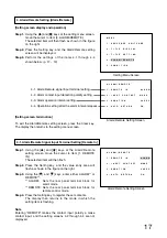
Page 17: ... signal input terminal setting 4 2 Alarm contact input detection polarity setting 4 3 Alarm operation interval setting 4 4 Operation setting after the alarm interval elapses 4 1 Alarm Remote Signal Input Terminal Setting Remote In Step 1 Using the and keys at the Alarm Remote setting screen move the cursor to Item 1 REMOTE IN The selected item will then flash Step 2 Press the Setting key and the v...

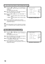
Page 18: ...1 4 The Remote Inputs are always activated when made A L A R M R E M O T E 1 R E M O T E I N A L A R M 2 I N P U T C O N T A C T M A K E 3 D U R A T I O N 2 0 S E C 4 A U T O R E T U R N O N Alarm Remote Setting Screen 4 3 Alarm Operation Interval Setting Duration Step 1 Using the and keys at the Alarm Remote setting screen move the cursor to Item 3 DURATION The selected item will then flash Step ...

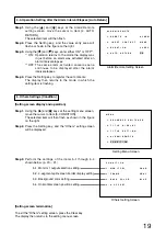
Page 19: ... 0 S E C 4 A U T O R E T U R N O N Alarm Remote Setting Screen 5 Others Settings Condition Setting screen display and operation Step 1 Using the and keys at the setting menu screen move the cursor to Item 5 CONDITION The selected item will then flash as shown in the figure on the right Step 2 Press the Setting key and the Others setting screen will be displayed Step 3 Perform the settings of the i...

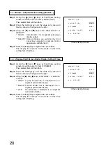
Page 20: ... E G R A Y 3 B A C K C O L O R B L U E 4 H O F F S E T Others Setting Screen 5 2 4 Segment Split Screen Border Display Setting Frame Step 1 Using the and keys at the Others setting screen move the cursor to Item 2 FRAME The selected item will then flash Step 2 Press the Setting key and the value entry area will flash as shown in the figure on the right Step 3 Using the and keys enter GRAY 1 or BLA...

Page 21: ...or QUAD The screen is set for a full screen display There are one or more channels without Video loss The background of the setting menu screen is always blue regardless of the background color setting C O N D I T I O N 1 M O N I T O R 1 Q U A D 2 F R A M E G R A Y 3 B A C K C O L O R B L U E 4 H O F F S E T Others Setting Screen 5 4 Horizontal Screen Position Setting H Offset Step 1 Using the and...

Page 22: ...ed cameras are connected video images may be distorted In such cases switch the camera synchronization system to internal synchronization mode Monitor TV Monitor TV Monitor TV BNC connector optional Single cable camera C QA40 C QA40 Separate room Camera Drive Unit VIDEO IN VIDEO IN VIDEO IN VCR IN IN IN IN OUT OUT OUT OUT CAMERA OUT CAMERA OUT CAMERA OUT CAMERA OUT GND Alarm input Camera 1 Camera ...

Page 23: ...E is selected and when the contact opens if BREAK is selected Remote setting Remote control operation is always performed when the contact closes Input signal specifications Alarm remote input signal pulse width Over 0 3 second Alarm remote input signal pulse separation Over 0 3 second Notes Do not apply the voltage to the Alarm remote signal input terminals Avoid connecting the Alarm remote signa...

Page 24: ...lphanumeric characters for each channel Synchronizing System Internal synchronization Automatic Sequential Automatic switching interval 1 60 seconds Skip function selection for each Switching input Operating Temperature 0 40 C Operating Humidity 30 90 no due condensation must be formed Range Finish Panel ABS resin black paint Case Pre coated steel plate black Dimensions 350 w x 44 h x 298 d mm exc...

Reviews: