background image

INTERFACE UNIT

C-RF1000

REMOTE 

CONTROLLER

POW

ER/D

VR

4

3

2

1

INTER

FACE

 UN

IT C-R

F1000

OPERATING INSTRUCTIONS

1. SAFETY PRECAUTIONS 

.......................... 2

2. GENERAL DESCRIPTION 

........................ 3

3. FEATURES 

................................................ 3

4. HANDLING PRECAUTIONS 

..................... 3

5. NOMENCLATURE AND FUNCTIONS

Front panel .................................................. 4
Rear panel................................................... 4

6. CONNECTIONS 

6.1. System Example .................................. 5
6.2. About connections ................................ 6

6.2.1. When connecting the C-RF1000 

to the Remote controller or PC ......... 6

6.2.2. When connecting the C-RF1000 

to the Digital Video Recorder ............. 6

7. RACK MOUNTING 

..................................... 7

8. SPECIFICATIONS 

...................................... 8

Accessory .................................................... 8

Thank you for purchasing TOA's Interface Unit. Please carefully follow the instructions in this manual to
ensure long, trouble-free use of your equipment.

TABLE OF CONTENTS

Summary of Contents for C-RF1000

Page 1: ...el 4 Rear panel 4 6 CONNECTIONS 6 1 System Example 5 6 2 About connections 6 6 2 1 When connecting the C RF1000 to the Remote controller or PC 6 6 2 2 When connecting the C RF1000 to the Digital Video...

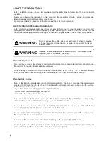
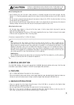
Page 2: ...onal injury and or property damage When the Unit is in Use If any of the following irregularities occurs immediately switch off the power disconnect the power supply plug from the AC outlet and inform...

Page 3: ...d in a commercial environment This equipment generates uses and can radiate radio frequency energy and if not installed and used in accordance with the instruction manual may cause harmful interferenc...

Page 4: ...from the PC This port cannot be used simultaneously with Remote Controller Input Terminal 4 5 DIP Switch Sets the transmission rate of both the Remote Controller input terminal and RS 232C port Note F...

Page 5: ...C DR091 and C DR161 Series Monitor Supplied modular cable 3 m 9 8 ft Interface unit C RF1000 AC adapter CPEV S 0 65 2C RS 485 control Line Remote controller 1 C RM1000 Remote controller 2 C RM1000 Re...

Page 6: ...settings 2 Remote Controller Input Terminal 4 cannot be used simultaneously with the RS 232C port Connect either 6 2 2 When connecting the C RF1000 to the Digital Video Recorder The maximum cable leng...

Page 7: ...ccessories of the MB 15B J 3 x 14 self tapping screw 3 x 14 self tapping screw Rack mounting bracket a Elevated Operating Ambient Temperature If installed in a closed or multi unit rack assembly the o...

Page 8: ...0 Power Source Current Consumption Digital Video Recorder Control Remote Control External Control Terminal Transfer Speed Setting Display Number of Remote Controller Connections Maximum Cable Distance...

Reviews: