background image

6

Step 4.

Mount the speaker.

Caution

Before mounting, check to be sure that the speaker's
3 mounting tabs are turned inside the unit as shown in
the figure.
If turned outward, the speaker cannot be inserted
through the mounting hole.

In

Out

Mounting tab

9 mm (23/64")

Step 3.

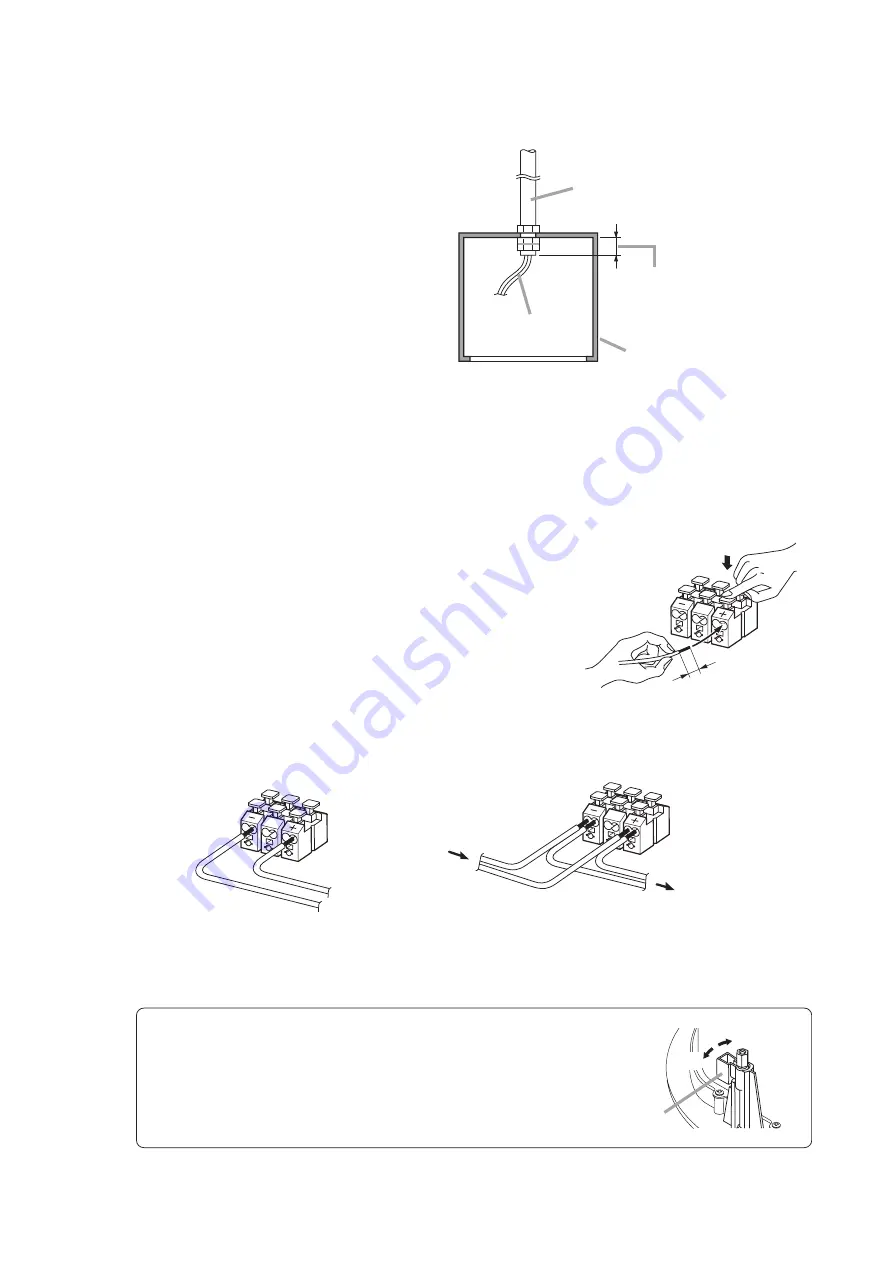
Connect the speaker cable to the push-in terminal. 

Tip

Use the 600 V vinyl-insulated cable (IV or HIV wire). 
The following matching cable types are recommended:

• Solid copper wire: 

ø0.8 – ø1.6 mm (equivalent to AWG 20 – 15) 

• Stranded copper wire: 0.75 – 1.25 mm

2

(equivalent to AWG 18 – 17) 

Press fully down on the corresponding terminal button and
insert the cable.

Tip

To detach the cable, press fully down on the terminal button
again, then pull the cable. 

[If bridging]

[If not bridging]

To the next speaker

From Amplifier

2-5.

Hanging from a ceiling suspension pipe (exposed installation) 

Use the optional HY-BC1 Back Can.

Note

Refer to the instruction manual included
with the HY-BC1 for Back Can installation.

Suspension pipe

Speaker cable

HY-BC1 (optional)

Caution

Ensure that this length is 
shorter than 53 mm (2 

3

/

32

").

[Installed HY-BC1]

(Example of mounting to suspension pipe)

Summary of Contents for F-2352SC

Page 1: ...MENSIONS 3 5 INSTALLATION 4 6 REMOVING THE SPEAKER FOR MAINTENANCE 9 7 REPAINTING THE SPEAKER 10 8 SPECIFICATIONS 11 Accessories 11 Optional Components 11 Please follow the instructions in this manual to obtain the optimum results from this unit We also recommend that you keep this manual handy for future reference TABLE OF CONTENTS ...

Page 2: ...rom the unit If no tone sounds Avoid installing the unit in humid or dusty locations in locations exposed to the direct sunlight near the heaters or in locations generating sooty smoke or steam as doing otherwise may result in fire or electric shock Do not operate the unit for an extended period of time with the sound distorting This is an indication of a malfunction which in turn can cause heat t...

Page 3: ...h mount ceiling speaker design employs unique acoustic construction to realize a wide area of coverage Uniform sound output levels are achievable not only directly under the speaker but also over a wide radius Because the speaker is provided with both low and high impedance operating capability it can be used in many different applications Front panel mounted input selector switch permits easy ver...

Page 4: ...TB1 Tile Bar Bridge Ceiling mounting in a larger than specified hole Use the optional HY RR2 in conjunction with the optional HY TR1 Trim Ring Mounting to an anchor bolt Use the optional HY RR2 in conjunction with the optional HY AH1 Anchor Hanging Bracket Hanging from a ceiling suspension pipe exposed installation Use the optional HY BC1 Back Can Mounting hole HY RR2 optional HY RR2 placed on cei...

Page 5: ... HY RR2 2 3 Ceiling mounting in a larger than specified hole Use the optional HY RR2 Reinforcement Ring in conjunction with the optional HY TR1 Trim Ring Note Refer to the instruction manual included with the HY TR1 for the correct ceiling mounting procedure Installed HY TR1 and HY RR2 2 4 Mounting to an anchor bolt Use the optional HY RR2 Reinforcement Ring in conjunction with the optional HY AH1...

Page 6: ...uivalent to AWG 20 15 Stranded copper wire 0 75 1 25 mm2 equivalent to AWG 18 17 Press fully down on the corresponding terminal button and insert the cable Tip To detach the cable press fully down on the terminal button again then pull the cable If bridging If not bridging To the next speaker From Amplifier 2 5 Hanging from a ceiling suspension pipe exposed installation Use the optional HY BC1 Bac...

Page 7: ...jury Rotate and tighten the mounting tab axis screws 3 places on the unit clockwise to their full stop in order to grip the ceiling panel with the mounting tabs Diffuser section Diffuser section Mounting hole Mounting tab axis screw Mounting tab Use an electric screwdriver to tighten Tightening torque 6 10 kgf cm 4 2 Exposed mounting in the case of Step 2 5 Use the optional HY BC1 Back Can To moun...

Page 8: ...to the speaker or amplifier Step 6 Attach the front grille Align the tabs 3 places on the back side of the grille with the corresponding notches in the unit then rotate the grille to full stop in the direction indicated by the LOCK arrow Tip The front grille employs a double locking system that clicks into place once partway through rotation but only locks into position at its point of full rotati...

Page 9: ...take care to rotate the grill fully counterclockwise in order to release the lock Mounting tab axis screw Mounting tab Use an electric screwdriver to detach Screw cap Caution Be sure to set the screwdriver s torque for under 4 kgf cm Failure to do so may cause the Screw cap and the Mounting tab to fall off on the rear of ceiling panel 6 2 Removing the Speaker Rotate the 3 mounting tab axis screws ...

Page 10: ... paints for the front grille grille and frame materials Grille Rolled steel plate Frame Fire resistant ABS resin acrylic paint Be sure to follow the directions indicated on the paint when painting Step 3 After the paint has dried apply another light coat Caution Repeating Step 2 apply two or more light coats of paint Application of one thick coat of paint all at once may cause drips or unevenness ...

Page 11: ...ous program 18 W 8 Ω 12 W 16 Ω Impedance 100 V line 1 7 kΩ 6 W 3 3 kΩ 3 W 10 kΩ 1 W 20 kΩ 0 5 W 70 V line 830 Ω 6 W 1 7 kΩ 3 W 3 3 kΩ 1 5 W 10 kΩ 0 5 W 20 kΩ 0 25 W 25 V line 830 Ω 0 75 W 1 7 kΩ 0 4 W 3 3 kΩ 0 2 W 10 kΩ 0 06 W 20 kΩ 0 03 W 16 Ω 8 Ω Sound Pressure Level 89 dB 1 W 1 m Frequency Response 80 20 000 Hz 10 dB 50 20 000 Hz 20 dB at installation in 1 2 free sound field Measured by install...

Page 12: ...Printed in Indonesia 533 06 094 8A ...

Reviews: