Operation Instruction Manual
TOA NEW 900 SERIES
MIXER PREAMPLIFIER
M-900A
1 6-channel
mixer
preamplifier
2 Wide
frequency
response; 20 — 20,000Hz, ±1dB
3 Low
distortion
and
noise
4 Parallel
operation of two mixer preamplifiers
5 Headphone
output
6 Bass
and
treble
controls
7
Tone defeat switch
8 Output
on-off
switch
9 VU
meter
range
switch
(selectable 4dBm/18dBm)
10 A
full
range
of
plug-in
modules
11 Balanced
and
transformer-isolated output of 150/600 ohms
12 Portable
or
rack-mounting type
The TOA M-900A Mixer Preamplifier controls and mixes up to six
independent input signals and delivers up to +20dBm of output
power. Optional plug-in modules are available for use with the M-
900A to provide versatility for a wide choice of operating applica-
tions. Edge connectors in the rear of the unit permit selection from
a wide range of TOA plug-in modules: the H-01 series, H-02 series
and H-03 series Microphone Preamplifiers, the E-01 and E-11 Mag.
Phono Preamplifiers for magnetic phono inputs, the X-01 series and
X-11 series Auxiliary Preamplifiers for high-level sources, the B-01
series and B-11 series Bridging Transformers for bridging high-
impedance lines, the L-01 series Line Matching Transformers for
matching 600-ohm lines, the I-01 Paging Input for combining with
TOA Intercom Systems EXES-1000, EXES-5000 and EX-16, T-01
series Line Outputs for matching 600-ohm lines and the S-01, S-02
and S-03 Tone Generators for generating attention-getting signals
and 1kHz sine wave for testing within the total system. Sources fed
to particular input module accessories are muted by short-circuiting
at MUTE TERMINAL on the rear. To perform this function,
Module E-11, X-11 series or B-11 series is required.
The TOA M-900A Mixer Preamplifier has a balanced and trans-
formerisolated output for operation with 600-ohm or 150-ohm
loads.
Other features include a tone defeat switch, an output on/off
switch, connections for parallel coupling of another M-900A or
Mixer Power Amplifiers A-903A, A-906A or A-912A, and monitor-
ing by visual and/or audio means.
Toa Electric Co., Ltd.
KOBE, JAPAN
1 3 3 - 0 2 - 7 3 6 - 1
Printed in Japan
Features
General Description
Summary of Contents for M-9000
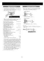
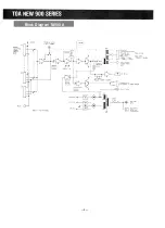
Page 6: ...Block Diagram M 900 A 5...
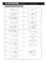
Page 10: ...Block Diagrams Plug in Modules 10...
Page 13: ...Schemiatic M 900 A...


