4
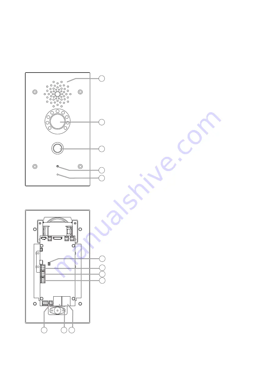
5. NOMENCLATURE AND FUNCTIONS
• Designed for wall-recessed installation (YC-400 is required.)
• Hands-free (with AEC function) type
• Call button x 1, Relay output x 2, External control input x 2
• PoE compatible (IEEE802.3af compliant)
• Equipped with a camera, luminance sensor, and infrared light (N-SP80VS1 only)
[Front]
1
2
3
4
5
6
7
8
9
10
11 12
1. Speaker
Outputs speech voice from the partner station during conversation.
2. Camera (N-SP80VS1 only)
A built-in camera with 3 mega pixels.
Used when making conversation with a multimedia station.
3. Call button
Press this button to start conversation.
Pressing this button will call the preset partner station.
4. Operation indicator
Lights or flashes during conversation or during a call from this
door station.
( The indication color and when the indicator lights or flashes can
be changed by the setting.)
5. Microphone
Picks up the speaker’s voice during conversation, which is then
sent to the partner station.
6. Reset button
Press this button to restart the station.
Holding down this button for 5 seconds or more restarts the door
station in the default state. (The settings data will be initialized.)
7. External control inputs 1 and 2
A special calling can be performed by connecting an external
control switch or sensor output to this terminal.
8. Relay 1 connection terminal
The relay output can be controlled by the specific dial code
from the partner station during conversation. Used to unlock the
nearby door. (An appropriate dial code can be set.)
9. Relay 2 connection terminal
Has the same function as the Relay 1 connection terminal (8).
10. DC power input terminal
The door station can be operated by inputting 12 V DC to this
terminal.
11. Ethernet connection terminal
Used when connecting to the network.
12. Ethernet connection terminal (PoE compatible)
Used when connecting to the network.
Power can be supplied when this terminal is connected to the
PoE switching hub.
[Rear]
The figure shows the N-SP80VS1.
The figure shows the N-SP80VS1.


