8
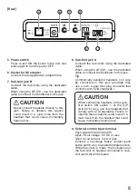
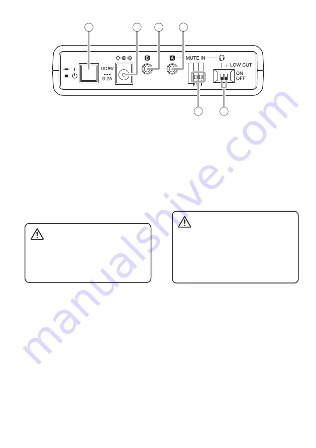
[Rear]
5. Power switch
Press to turn ON the power to the unit, and
press again to turn the power OFF.
6. Socket for AC adapter
Connect the designated AC adapter here.
7. Sub-Unit jack B
Connect the Sub-Units using the dedicated
cable.
When using the NF-CS1, use the dedicated
cable to connect the Distributor to this jack.
Never connect headsets directly to this
jack. Failure to observe this caution
could result in a loud noise from the
headset that could cause momentary
hearing loss.
CAUTION
8. Sub-Unit jack A
Connect the Sub-Units using the dedicated
cable.
When using the NF-CS1, use the dedicated
cable to connect the Distributor to this jack.
Tip
Commercially available headsets can also
be connected to this jack (provided they
use a ø3.5, 4-pole mini plug connector that
conforms with CTIA standards.)
When connecting headsets to this jack,
first switch ON switch 1 of the DIP
switch (10). Also, use only headsets that
comply with CTIA standards. Failure to
observe these cautions could result in a
loud noise from the headset that could
cause momentary hearing loss.
CAUTION
9. External control input terminal
Push-type terminal block (2P)
Open circuit voltage: 9 V DC or less
Short circuit current: 5 mA or less
Connect a no-voltage ‘Make’ contact (push
button switch, etc.) to enable the Mute function.
While the circuit is ‘made,’ the microphone of
the Sub-Unit or headset connected to Sub-
Unit jack A (8) will be muted.
5
6
7
8
9
10

